Personal Home Page | Business Home Page | Resume
Ham Radio Projects Page | Computer Projects Page | Telesaver Projects Page | Project Chronology Page
Projects
or... wandering around the house, finding stuff that any normal person would have thrown out decades ago.
Take a walk down memory lane with me!
Many of these photos were taken in 2010 -- so the subjects don't look quite as nice as when they were built (:>).
Earliest
The earliest thing I can recall constructing was this opaque projector. I seem to remember being in the third grade, which would put it in 1963:
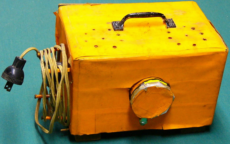
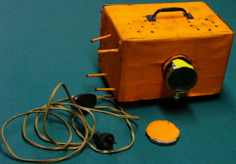
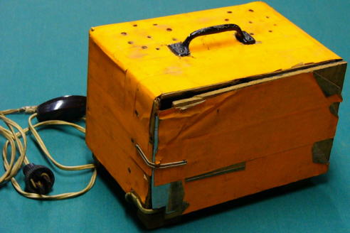
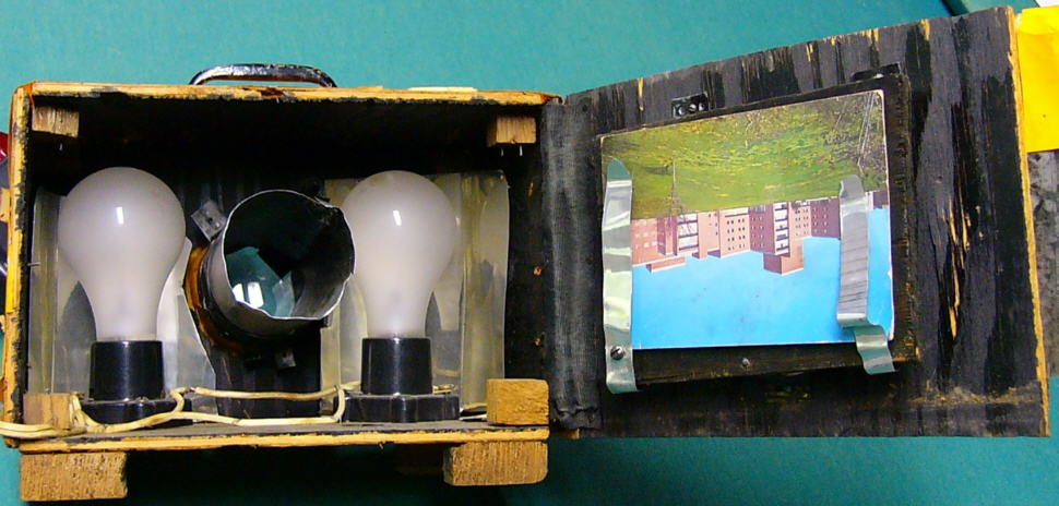

I found it in The Boy Electrician (below, page 371). The postcard inside is from June 1960, but maybe the card was old? My big brother thinks I was in first grade, but I can't imagine I really built it as a six year old.
It used two 100 watt lightbulbs and it got quite hot, even with the airholes at the top.
Commercial opaque projectors use a reflecting mirror to re-invert the image, so postcards (which it was designed for) had to be placed upside down,
and writing of course came out backwards. The projected image at the right is barely visible because my digital camera won't let me expose it long enough.
Not worth pulling out my old 35 mm SLR and develop real film!
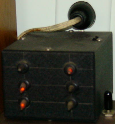
An Idiot Box from some time in the 1960's: all it does is flash neon lamps. It's just three sets of relaxation oscillators made up purely of neon lamps, resistors, and capacitors.
Originally it used high voltage "B" batteries, but later I changed it to run off of the 120 VAC powerline.
I remember building this crystal radio in 1966:
 Most of the parts have since disappeared, but it had an RF filter cap and a germanium diode (plus headphones). I'm not so old that I had to actually use a galena crystal with a cat's whisker!
I ran about a 50 foot wire from a second story window out to the backyard, and could pick up quite a few Baltimore AM stations.
Other early projects: I built lots of stuff from Alfred P. Morgan's The Boy Electrician which I found in the library. A pdf of the book is here. I definitely built the microphone which is shown on page 175, but it wasn't quite like he shows it: I cut open two D batteries and removed the center carbon post (did a lot of that). Mounted them horizontally on the top of a cigar box, and laid a length of mechanical pencil graphite across the two posts. Then just put a battery and headphones in series with the contraption. I remember showing it in fifth grade, so that would be 1965.
I built the transformer shown in page 226. It seems crazy, because in the 1960's you wouldn't necessarily find the kinds of stores Morgan wrote about originally in 1913! But I found a sheet metal shop within walking distance, and the guy cut up hundreds of rectangular pieces for me. Couldn't have cost much as I was a little kid. Somehow found the copper wire, too. After building that one transformer, I decided I'd just get ready-made ones in the future.
Built many electromagnets (remember the large cylindrical 1.5 volt batteries with thumbscrew connecting
I did make a "bullhorn" which was a transistor amplifier wired to a speaker. I was definitely not impressed with the loudness, it was probably 100-200 milliwatts.
I had an intercom system on several floors of the house, probably when 11-12 years old.
Speaking of transistors, I struggled to understand them. All the books said you put current in the base-emitter junctions, and you got amplification at the base-collector pins.
I don't know how many transistors (they were all germanium in those days) I blew out in the 1960's, because I put a battery directly between the base and emitter (properly forward biasing it) and a DC motor at the base-collector;
I expected the motor to turn faster than without the transistor. Never happened. Eventually I learned the difference between power generation and control modulation!
ElectroChemistry:
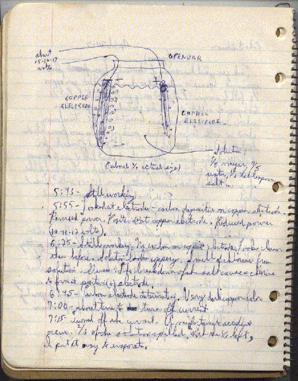
I seem to have been fascinated with breaking down aqueous molecules with electrolysis. I have a spiral notebook with entries dated April 7, 1967 through February 24, 1968 -- 72 handwritten pages in all. I filled gallon glass jugs with hydrogen, oxygen, chlorine, and who knows what other gases. You know the hydrogen test of putting a match under a small inverted test tube and getting a crack or popping sound from the combustion? I did that with gallon glass bottles and got a big (BIG) wooof! and lived to tell with no mishaps... mishaps... mishaps

Moonshine
This doesn't really belong in this section, but it's chemistry. In Drew Wolfe WA3KLK's high school chemistry class, we fermented various fruits and distilled the mash into wine. But I double-distilled (maybe triple?) mine! The result was probably near 100% ethyl alcohol. "Teach" advised us not to sample our wares, we were aware of potential serious health issues. But we were high school kids! Are you kidding me? I did take one sample (back then) and found it to be quite potent. I was already wearing eyeglasses and didn't become any more blind. This is the actual booze.
Yes, yes, I know -- you don't have to tell me. The fact that I still have this proves that I'm certifiably crazy!
Plumbing
Originally I had an old large pressure tank, and lots of salt and neutralizer equipment for my well, all from the original construction in 1966.
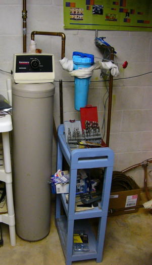
In 1992 I removed the neutralizer and salt equipment, and installed the neutralizer (tan, above left).
Also added the whole-house water filter (blue device to the right of the neutralizer). I still have a heck of a time getting compression fittings to completely seal,
always afraid if I tighten any more it's going to strip the threads. I figure if the socks let the very very slow leakage evaporate before it drips, that's good enough for me.
I had repeatedly patched pinhole leaks in the pressure tank until it seemed to be more patches than intact metal, and was afraid it would simply disintegrate one day.
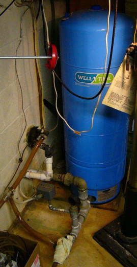
So in 1996 I removed the original pressure tank and replaced it with the physically smaller (but equivalent) Well-X-Trol tank with an internal bladder (blue, in center).
The original tank was to the left, can still see the circle on the floor underneath the sock in the center picture. Came up with a mixture of galvanized pipe fittings to connect the new one.
The copper pipes from the inlet to the neutralizer periodically develop pinhole leaks; I put rubber gasket material and hose clamps on as a temporary fix until I can't stand no mo' --
and then depressurize and replace offending pipe section. The sock in center picture removed after such replacement in August 2010 when pic taken.
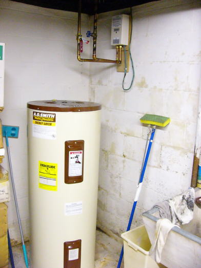
In 1993 my electric water heater started leaking and replaced it with a standard 55 gallon unit (A.O. Smith tank in right picture). All of the major work above done with K3VC's help (a real plumber).
Automatic Well Pump Shutoff
I had a bad pipe leak and it ended up filling the basement with water before I noticed it and shut off the well pump. So, like closing the barn door after the horses had escaped, in September 2010 I installed an automatic well pump shutoff system. I bought a Basement Watchdog Water Alarm ($10 at Home Depot). It operates off of a 9 volt battery and has contacts on its bottom (which can be detached from the unit). When water on the floor is detected, it emits a high-pitched warning sound. I was very impressed: with no alert active, my DVM could measure no current drain! So it was less than 0.1 ua. It draws about 13 ma. when active. All in all, quite power conservative.
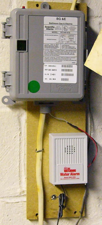
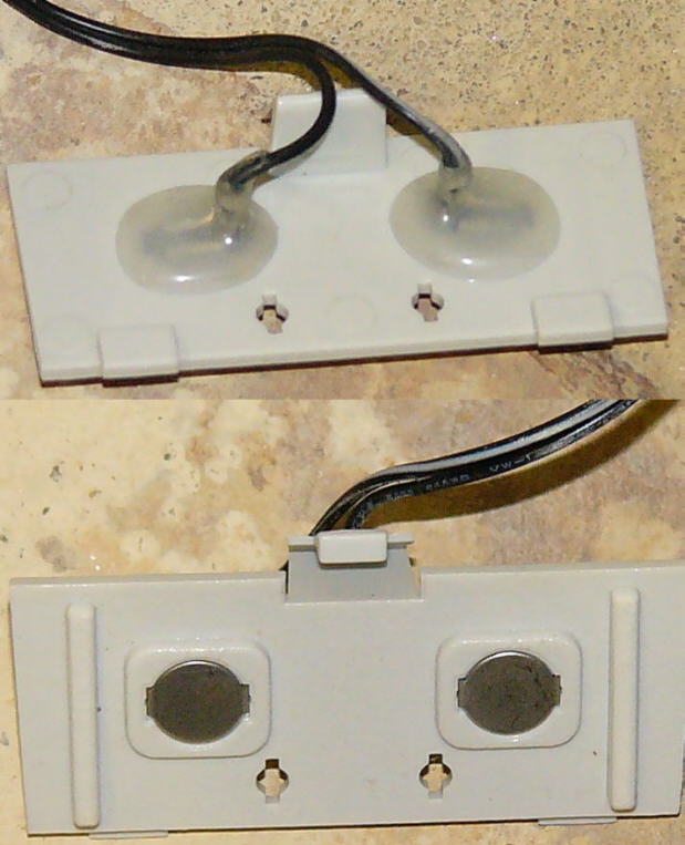
I designed a simple circuit with two optocouplers to detect the current drain when active and latch an output once tripped.
I wanted to be able to disable the well pump, which draws 9.6 amps @ 240 VAC, and was looking around for a relay which had hefty enough contacts in the normally-closed configuration.
I found a discarded air conditioner contactor, but it only had normally-open contacts and its coil was driven with 240 VAC itself.
I suppose I could have used it and powered the coil from the output of the pressure switch (which would only turn the contactor on while actively pumping), but I'd still have to drive a 240 VAC coil.
Then I found a discarded BGE (electric power company) radio unit designed to receive signals to temporarily disable an electric hot water heater during high demand periods.
It had exactly what I needed: a relay with normally-closed contacts with plenty of current/voltage handling capability, with a 12 VDC @ 100 ma. coil!
But instead of just taking out the relay, I saw that the box itself had a built-in 240 VAC in/12 VDC out power supply. Plus a convenient box to build it in! Just what the doctor ordered.
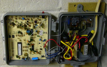
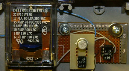
I just cut the 240 VAC feed going to the pressure switch (which in turn drives the well pump motor) and fed it through the new box.
The little protoboard on the right is my addition to the circuitry, it literally just contains two opto-couplers. I re-routed the relay coil to be driven by my circuit instead of the original receiver.
I powered the Watchdog Water Alarm from the 12 VDC ac supply, so no need to worry about batteries going bad.
Plus didn't even have to open the Water Alarm box, as the opto-coupler simply senses the power drain to the battery jack.
I added an LED (at the top, illuminated in the photo) to show that the relay has latched (and the power feed is inhibited).
To reset the circuit, I just need to temporarily remove power -- and there's already a switch on the wall that does that.
So the next time there's any type of leak in this inlet area (copper pipe pinholes most likely) at least it can't do too much damage -- plus I'll be alerted by the screech sound.
Here is the drawing.
I also put another Basement Watchdog by the basement door to alert me in case my outside pump gets clogged up. I used an AC adapter to power it instead of a battery.
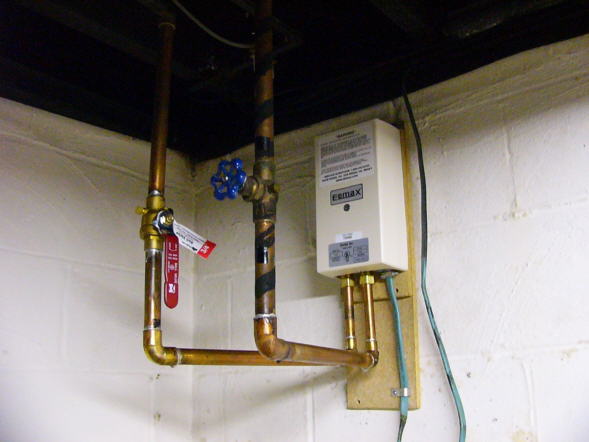
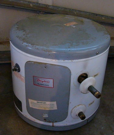
In March 2009 the main (A.O. Smith) water heater from 1993 started leaking. Instead of replacing it with another similar unit, I did away completely with a tank-based system.
Installed the on-demand Eemax EX95 "Flow Controlled" Electric Tankless Water Heater instead (above left, also above the A.O. Smith tank picture).
It draws 40 amps @ 240 VAC (9600 watts!) -- but only while the hot water is actually being used. This has saved on my electric bill.
I know how to solder wires, but have never been too good at soldering copper pipe. Managed to cut out the original piping and put in the U-bends to the Eemax heater
with no leaks, pleasant surprise. That solved half the problem.
There is a long pipe run from the main water heater to the upstairs bathrooms, and it always took a good two minutes to get hot water there.
Originally there was a small electric tank heater in an alcove behind a bedroom closet (above right) which was fed from the main heater.
Only a few feet from the bathrooms, this gave a fast heat response. Too bad that heater had been broken for many years.
I would have replaced it eons ago, but all of the fittings were corroded, and access to the tiny spot through the closet made me fearful that I'd make
matters worse if I tried to remove it. But the EX95 in the basement doesn't have enough oomph by itself to satisfactorily power a bathtub fill or shower.
I took the opportunity to finally address the small water heater failure by replacing it with an Eemax EX65T tankless unit. This device is microprocessor controlled (PWM) to maintain a constant output temperature.
(The EX95 isn't, it heats the water as much as it can as it flows.) Necessary, because it is fed from the EX95 and the two together could possibly boil water.
It draws 27 amps @240 VAC (another 6500 watts!). I put a low-flow aerator on a bathroom sink which manages to provide just enough flow to activate the EX65T,
but is below the activation threshold of the EX95. Which accomplishes two things: (1) it saves power, because the main unit is not turned on (which would be useless anyway
because you finish handwashing before the hot water makes it upstairs to the sink); and (2) it keeps the flow rate low enough so that the EX65T by itself can heat the water sufficiently.
It's still necessary to wait a couple of minutes for both heaters to contribute to showers or tub fills to handle those rates. In all, this combination has proved satisfactory,
though not really quite as good as a tank heater. To be fair, the EX units are not rated for whole-house usage, but the stronger unit takes three 240 VAC 40 amp feeds,
which would have been more aggravation at the circuit panel. As it was, I was able to re-use the 240 VAC line to the main water heater
but had to run a new 240 VAC line to the EX65 (there was only 120 VAC in that location).
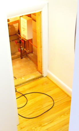
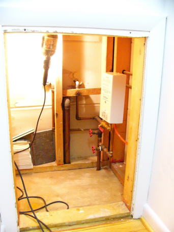
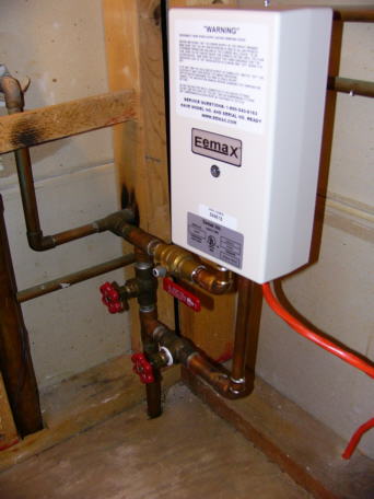
It was a challenge to do the pipe work in the alcove (above), especially as it's impossible to see all around the pipes that need soldering.
The hardest part was loosening the nonfunctioning existing valves in order to replace the washers. Successful on one (you can see the plumber's tape on the lower one),
I replaced the upper with a ball control type, and gave up on the bypass valve in the back which seems to be stuck closed which is what I need anyway.
I'd much rather work with electronics!

Reliability. The heating element in the main water heater opened in September 2010, 18 months after installation. The warranty is for one year. Concerned that this might be a recurring problem, I phoned tech support. Apparently they had made some unspecified changes in the design, and they sent me a free replacement element. Actually quite easy to repair the element anyway: the resistance wire (like a toaster's coiled spring) broke at the mounting screw. Just re-wrap on the screw. So I now have a replacement ready for next time. Repaired again 10/2014, and 6/2017; EX65T 2/2019. While it is easier to repair than with a traditional tank water heater which has to be drained first, it is a bit of a challenge to get the element out of the unit: twisting with a crescent wrench while pushing up with a screwdriver works.
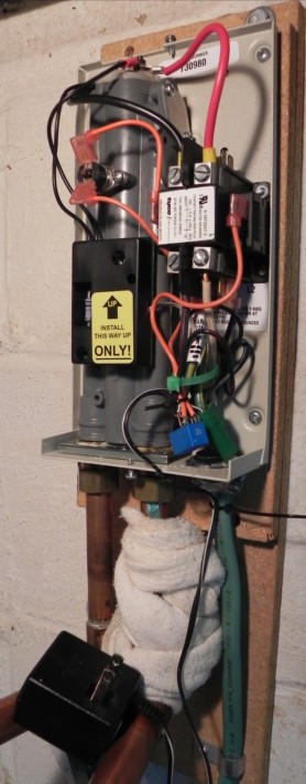 Marey ECO150. On 8/21/2021 the heating coil on the downstairs EX95 opened again; no big deal, I now can repair it pretty quickly. Which I did by re-wrapping around the screw. But this time when I put it back together, the water flow sensor seemed to have failed. Turning the faucet on caused the unit's contactor (big relay) to chatter instead of clicking on (and off with faucet close). And it wasn't heating the water. This didn't portend well! So I took the heating coil element out again, and now it was decimated -- into many, many small pieces. At this point I didn't know how it actually worked, and thought that perhaps the small broken coil pieces were clogging a magnet that moves with the water. This coil was beyond repair, so I put in my only spare element. Now, after re-connecting, I posted a helper at the circuit breaker box; turned on the water, it chattered, and immediately had the breaker turned off. (The contactor didn't cease chattering with the water off.) My hypothesis was that the chattering contactor somehow destroyed the first heating coil, and I wanted to save the one good coil I had left! I can understand the coil opening if it didn't de-energize fast enough with the water flow stoppage; I still don't understand why it totally destroyed the coil, though. Anyhow, the circuit breaker action was in time to save this coil from burning out (which I checked with an ohmmeter instead of removing the element). Now I had to figure out how to address the water flow detection problem!
I thought that the two light reddish wires about a third of the way down at the picture on the right was the output of the water flow sensor; I removed it and found that it was in fact an overheat detector, to remove primary contactor power if the unit gets too hot. Not what I was looking for. The only other possibility was the black module labeled "UP." I found that this contained a conformally coated circuit board which was right against the heating tube. I figured that there is a magnet that rotates inside the chamber when water flows. There are two magnetic reed switches mounted on the circuit board which clearly pick up the motion signal from the magnet. Something had failed on the detector board. It contained a couple triacs, high voltage transistors (L601E3, Q601E3, 7G30W, 7J2UE) along with an MC14541BCP CMOS counter and other circuitry. I didn't see any shorts on the triacs or the transistors and I broke one of the transistors while removing it to be able to properly test it. Checked my junkbox and I didn't have any similar high voltage parts (240VAC) anyway. This was a Saturday and I didn't have hot water (but I really only use it for the kitchen sink and showers/baths, the upstairs heater is sufficent for the bathroom sinks). I really wanted to get it operational somehow. I did send a request to EEMax but of course no response.
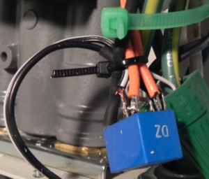 To this day I don't really know what all the stuff on the circuit board does; but (with power off) I put an ohmmeter on the two reed switches as I opened and closed the faucet. I found that one seemed to reliably close with water flow and open quickly when turning the water off. The other one closed with water flow but stayed on when I turned the water off -- until I physically moved it farther away. So after giving up actually repairing the board, I decided to build my own simpler circuit. It's an exaggeration to call it a circuit! Even though the contactor coil didn't draw much current, I didn't have any sufficiently high voltage opto-isolators to drive it. I do have some known relays that are rated at 120VAC, but I figured no particular point in using one of those; I did have an unknown ratings relay with a 12VDC coil (blue at right), it's probably 120VAC also. I removed all of the wiring to the black module (the two black wires remaining simply drive an LED from the actual heating coil voltage and have nothing to do with the water flow sensing). My trivial circuit just put that one reed switch in series with the contactor coil and an external 12VDC power wart. I wired the two 240VAC wires through the normally-open relay contacts to the contactor coil. Since I had bypassed the fuse that was on the circuit board I was a little worried, so I put a 1A circuit board type fuse in series with the 240VAC as well. This is only the coil side of the contactor, the output is left alone and is powered directly from the feed. Without power to the heating coil, the contactor reliably clicked on with the faucet opening and off with the faucet closing; I felt satisfied enough so I restored the wiring and now I had hot water!
This "fix" will probably work fine forever, but I remain a bit nervous about the missing detection circuitry. On the other hand, the worst that can happen is that the heating coil is energized with the water off and it will burn out the coil -- just as has already happened four times on this unit in 12 years. I eventually reached an EEMax tech on the phone (I'll skip the details on that). He said both the detector module and a replacement element are $56. Seems kind of expensive for the coil, though. The EX95 is discontinued but its replacement model uses the same element. So I started looking into other options.
I decided to switch out the EX95 with a Marey ECO150. While the system I had installed in 2009 worked, it had two deficiencies: the kitchen sink would get too hot to wash dishes at times; and one had to fiddle with the cold/hot mixture while leisurely taking a shower. The first problem is probably because I changed the kitchen faucet and I think it has lower flow than the original (which increases the temperature). The faucet is a single-lever type, and turning it a bit to the colder side lowered the hot water intake below the EX95's detection threshold; so the water would then become all cold and I'd have to repeat the cycle. The shower inconvenience is because I'm on a well, and the pressure tank cycles between 30-50psi. I had thought that because the EX95 drives the EX65T -- which is temperature controlled -- it would be okay. Now I believe that when the pressure is at 30psi and with a water-restricted showerhead, the EX95 was probably making the water too hot; the EX65T can't cool the water. This necessitated adding cold water, but when the pressure went up to 50psi the EX65T was regulating again and now there was too much cold. If originally I had gone with a temperature-regulated EX95T instead of the unregulated EX95, both problems might have been alleviated.
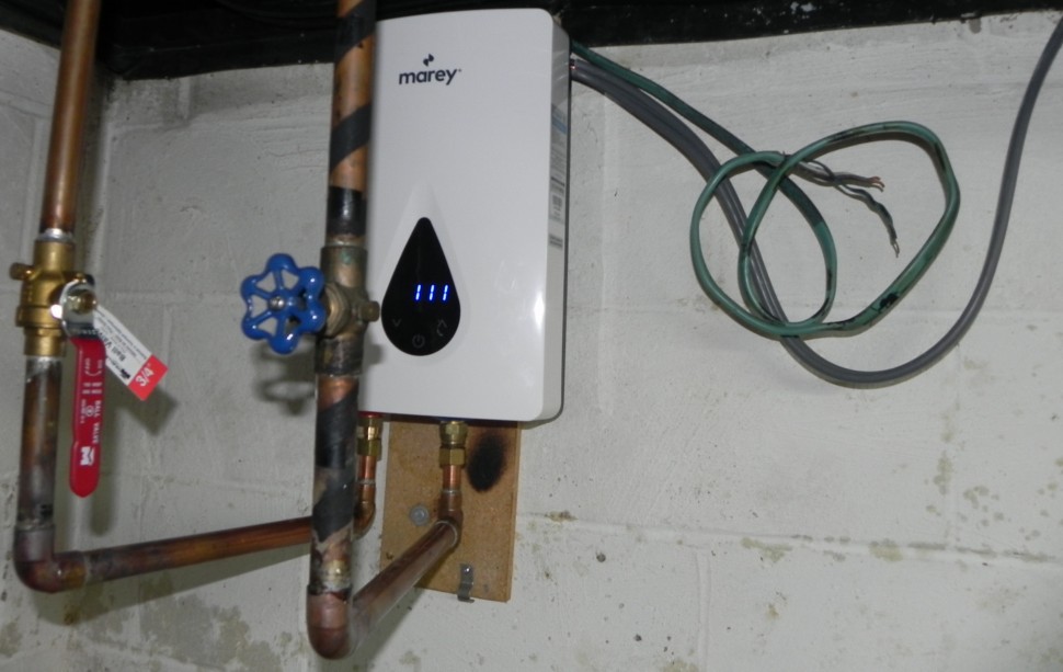
The ECO150 is regulated, and the temperature is set with a front panel control in degrees; the EX65T just has an internal potentiometer that has to be adjusted with trial-and-error. It also can consume up to 15KW as compared to the 9.5KW of its predecessor. It still uses a single 240VAC feed, but instead of a continuous 40A it can go up to a max of 60.8A. They recommend #6 wire, but I have #10 from the original tank water heater. I figure I'll see how it goes. I measured about an 8V drop with a full bathtub load; that's probably the only time it would be out of regulation, but I don't think it is even for that because the front panel temperature reading doesn't drop from its setting. And it is unlikely that I'd ever actually reach the max 60.8A draw as it'd be regulating in most instances. So I kept the 60A circuit breaker I already have instead of swapping it out for a 70A one which they indicate (circuit breakers notoriously need a lot more than the rated current to trip). Should I find it trips it's easy to put in a bigger breaker.
[10/5/2021 Update: Trying to remember my thinking when I installed the EX-95 -- EEMax suggests #8 wiring which is one step larger than the original #10; I had left it alone in 2009. But I checked that #10 Romex to the Marey unit after a bath fill and it wasn't warm -- it was hot! Not enough to burn down the house, but still... So I went to the bother of replacing it with the recommended #6. Which is quite unwieldy to manage. In the above picture you can see the old defunct wiring next to the new run.]
I was hoping to be able to mostly keep the plumbing (which would also mean it would be easy to swap the EX95 back in if the ECO150 failed); alas, the inlet/outlet are farther apart than on the EX95. The Marey unit is much larger than the EEMax, and the mounting configuration had the water connections farther out from the wall. Which meant that I would have to actually remove the pipes, cut them, and re-install instead of just swinging one of them outward a bit. Then I had a surprise problem: both units connect to 1/2 inch copper, but the EEMax has pressure fittings and the Marey fixed pipe threading. A trip to Home Depot found nothing; the floor helper actually sent me to Lowe's. Also found nothing in Lowe's. This was another Saturday, so the following week I went to a local plumber-supply store and found exactly what I needed for $6 total. I don't understand why Marey uses non-pressure fittings because with fixed pipes how does one disconnect? I'm not a plumber. So I did the dreaded pipe work. After three tries it didn't leak. I adjusted the temperature setting to 111 degrees (was trying for 110 but it jumps up and down several degrees at a time with the two buttons). The good news is that both of the identified problems are now gone! The idea is to set the hot water no hotter than is needed; then I only turn on hot at the faucets. The Marey unit seems to have a lower turn-on threshold than the EEMax, which in general is good. But now the discussion above about having the downstairs heater to not be triggered by the one low-flow bathroom faucet is out the window. Can't have everything!
My DVM has a temperature attachment, so I measured the water temp at the laundry room faucet right next to the heater, upstairs in the kitchen, and at the bathroom faucet. The Marey heater has a a somewhat under-damped feedback loop; you can see the temperature reading on the ECO150 go up and down as it adjusts. Sometimes it goes up to 118 or thereabouts, but it eventually stabilizes at the 111 setting. I found the same results at all three faucets with the DVM. I'm kind of surprised that there doesn't seem to be a temperature loss through the house. I guess the copper pipes just heat up to the water temp; I would expect there to be some loss from atmospheric conduction.
I did the switchout on September 8, 2021. I am hoping that the Marey unit will have better reliability than the EEMax; it seems to be heavier duty. I telephoned Marey and they do sell replacement pieces, but a casual inspection doesn't indicate what might fail. Figure I'll investigate that if/when the time comes. It has a 5-year warranty, but that doesn't particularly help when you want hot water NOW.
Basement Doorway Drain
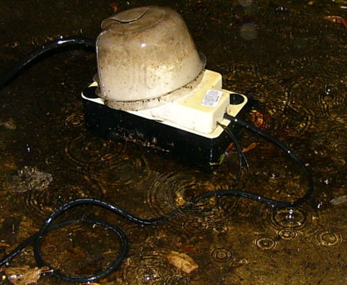
My basement doorway has a drain, but where it goes, nobody knows. It does work after a fashion, but usually quite slowly. During heavy downpours the stairwell water level rises until it sometimes goes over the lip and leaks into the basement proper. I've bailed and mopped not that often, but more times than I'd prefer! In July 2009 I bought a central air conditioning condensate pump. I cut out a hole at the bottom on the box's side and covered with a filtering screen. Attached more ballast (35mm plastic film cannister) to its internal float to get it to trip at a lower water level than normal, and adjusted the microswitch activation hookup to change the hysteresis amount. Had to install a 120 VAC outlet outside the door, too. There's a plastic hose that takes the outflow away from the stairwell. So when the water level rises (but not to the lip's height) the pump activates and pumps the water away until it leaves a small residue. It works fine, but the biggest problem is that I have to clean it every once in a while or it gets clogged up with dirt prevalent in the woods.
Dishwasher
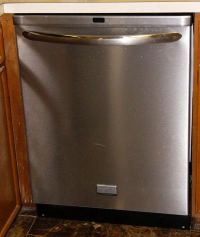
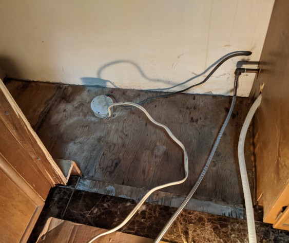
I had repaired my original 1967 model Tappen dishwasher over the years, but it was time for it to go. So in November 2010 I bought a new one. My biggest concern was that the kitchen floor was now a little higher than before because in 2008 I had had marble tile installed. I wasn't sure if I had the clearance to get the new one to slide into the space below the countertop before it would drop down off the edge of the marble. Inspecting the manufacturer spec sheets shed little light as they were incomplete. I just decided to go with hope and figured as a worst case I might have to remove a number of tiles to get it in and reglue them afterwards. Turned out there was sufficient clearance even with the new tiles. The biggest part of the job was rearranging the plumbing feeding the unit, as the connecting point was in the rear instead of in the front. Had to do soldering in the far back of the wall where I couldn't see behind the pipe. But it worked out!
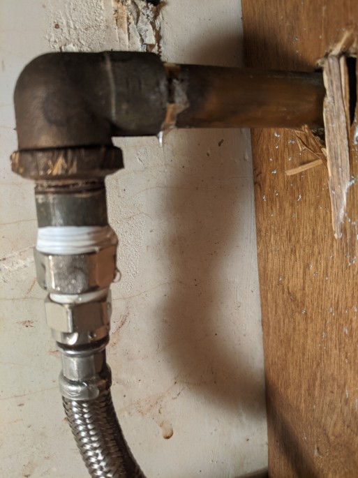
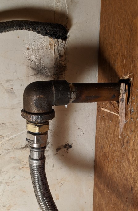
...until August 2022! I found water coming from the laundry room ceiling (below the kitchen). Took me a bit to determine where the water was coming from -- the pipe connection to the dishwasher (which of course is hidden). Pulled the unit out from its spot. Left below is the original arrangement I had come up with in 2010, which now was dripping. The 1/2" copper is soldered to an elbow to fit a 3/8" threaded double nipple, which connected with a conversion fitting to match the flexible hose to the dishwasher itself (this fitting I think came from a dishwasher install kit). There is a washer in the larger section of this adapter, but it wasn't flat so I couldn't locate a replacement. I managed to get another equivalent fitting at Home Depot. But it still leaked. I was using teflon tape. Bought some pipe dope and tried that instead. No dice. Then I noticed that the threaded pipe itself was corroded and there was a small hole in it (so close to the end that it looked like the adapter/pipe connection was leaking). Got a replacement iron nipple pipe, was confident that would fix everything. I was wrong. Tried both the old and new adapter, but the washer just slid inside the threaded nipple section when tightened (must have been lucky in 2010, or maybe the original one had a flatter end to stop the washer from creeping in). No matter what I tried it still leaked, and I was becoming despondent. Back to Home Depot (fourth visit). Was going to get a brass version of the threaded pipe which had a larger end that I figured would secure the washer between it and the adapter (I believe that would have worked). But instead, I found a brass threaded coupling which had one end that matched the elbow and the other end that matched the flexible hose. So I could eliminate the adapter completely, always preferable -- less to leak (below right). Ta Dah! Works fine. I should check again in 12 years.
Kitchen Sink

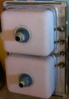
My kitchen sink (above) was the original install from 1967. I scrubbed it, but it still didn't look that great. The faucet was corroding and beginning to leak. So in November 2013 I figured that I might as well replace the sink along with the faucet. The plumbing didn't have shutoff valves at that point, either. So I shut off the main supply, sawed off the hot/cold pipe feeds, and unbolted and pried the whole sink assembly out of the countertop. The new faucet uses a flex hose coupling, so all I had to do to update the plumbing arrangement was to unsolder the size reducer and attach new shutoff valves with a wrench. Much easier than replacing the dishwasher plumbing -- when I had to solder a new pipe configuration underneath the counter somewhat blindly. The original sink had a 6 inch depth and it was hard to tell how much clearance I had for the existing plumbing underneath because in addition to procuring the sink itself the drains have to be bought separately and mounted in the drain holes -- with differing heights. So I bought a new sink with a 7 inch depth. When I dropped it into the spot (after I had to enlarge the opening in the countertop a fraction of an inch with a saber saw) I saw I had an extra inch. So I returned that sink (it also had a minor ding on it that was undesirable) and bought an 8 inch depth version. The vertical height was then very close to the original, but amazingly the horizontal space between the two drain pipes was longer than the original! For the same size sink??? So I had to discard that drainpipe connector and put in a new one.
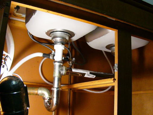
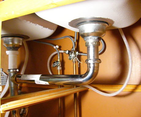
Here's the completed job:


I like the faucet and the sink looks great. But even though the actual double sink dimensions are identical to the original, this new one has more rounded corners. So pots that could lie flat before now do not. Oh, well!
Remodeling
In 1983 I put self-stick vinyl tile down on the unfinished basement clubroom cement floor.
Then I put up faux brick wall paneling in the clubroom to match the actual fireplace brick. Thankfully, the studs separating the clubroom area from the rest of the basement were already there.
Installed a bunch of fluorescent light fixtures on the ceiling.
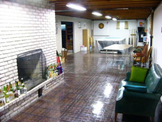

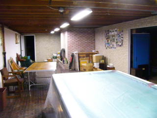
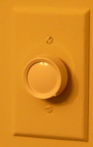
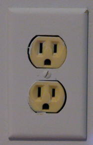
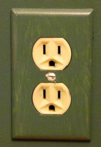
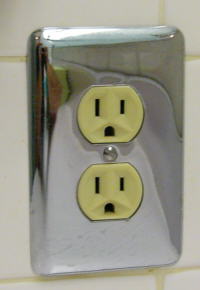
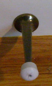
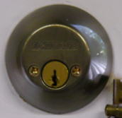
At the end of summer 2008 home remodeling, replaced every single door knob, lock, switch/outlet cover, and doorstop in the house:



Washer/Dryer Wiring
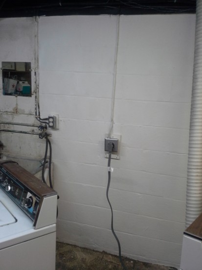
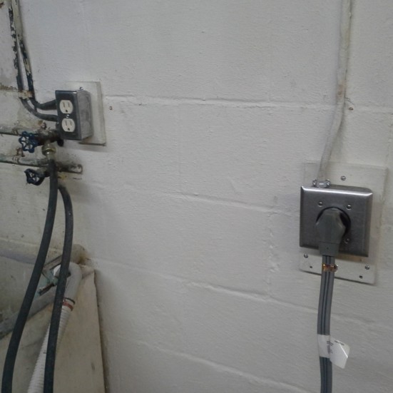
The wall in the laundry room gets damp from moisture seeping through the cinderblock. The outlets for the washer and dryer were mounted directly on the wall and the dampness corroded the outlet boxes to the point that the 240VAC dryer wouldn't operate. In August 2017 I pulled the washer and dryer away from the wall and cleaned and painted it with Drylok Masonry Waterproofer to seal it off for a while (like I had the semi-finished clubroom done professionally in 2008). Then I wired up new 120VAC and 240VAC outlets for the washer and dryer -- but this time I mounted them on wood blocks to hopefully keep the moisture out of the wiring.
Lazy Boy

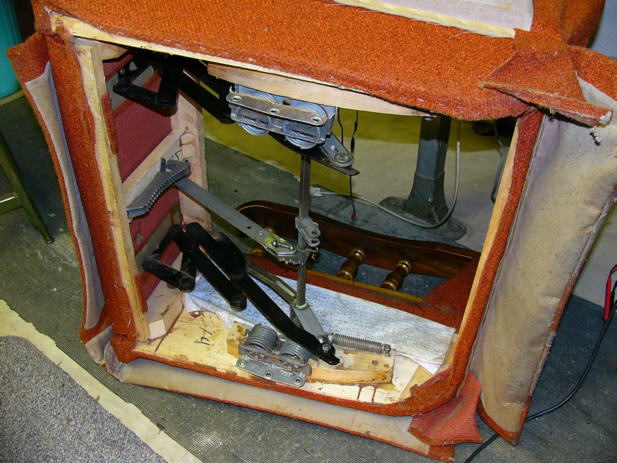
It felt funny sitting higher than I'd become accustomed to with the broken springs! Very pleased with the result. But it was a bigger job than I had anticipated.
Woodworking
I believe it was in eighth grade shop class (1968) that I made these:
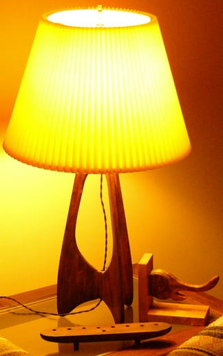


The lamp stand was a standard project(?), but I made the elephant and menorah for fun. Might have been ninth grade. Also made a necktie rack and a segmented dog in the seventh grade which I can't seem to find.

I know this doesn't belong here because they're not wood -- but I made these in ninth grade metal shop.
That's a combination hammer/screwdriver and a bottlecap opener.
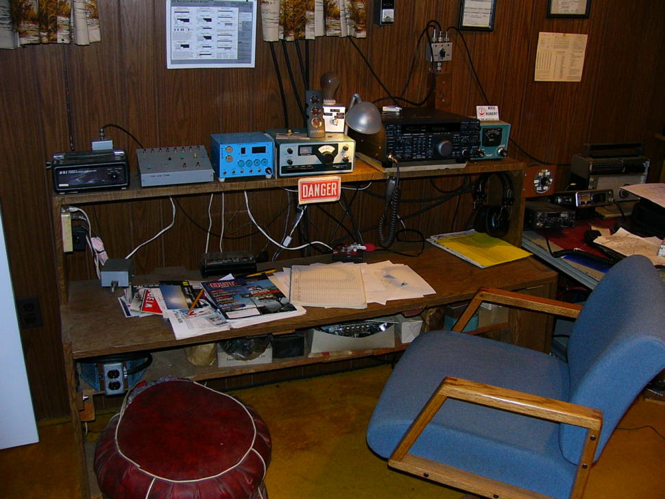
I built this ham shack bench in 1969 and still use it. Very easy, since I covered it with contact paper instead of properly finishing the wood!
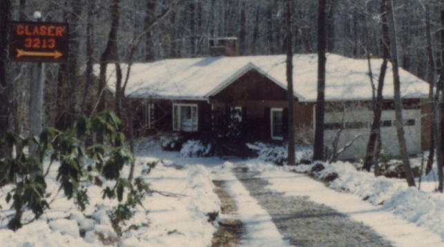
In 1983 I used my scroll saw to carve out this wooden road sign.
Painted it with fluorescent orange paint -- it was illuminated at night with a (regular) floodlight.
Even though I had layered it with protective spray lacquer, it needed regular repairs due to wood deterioration from its location in the damp woods.
Eventually it decomposed so much that I replaced it with a metal version.


I had more books than would fit on my three purchased bookshelves, and the ceiling left more room...
so I built three "additions" for their tops to give me seven shelves each. At least I bothered to stain and lacquer them!
(In the 1985-1995 timeframe.) I had them all stuffed overfull; after the onerous task of boxing everything up to empty the room for remodeling (2008), I never fully unpacked and replaced all of the books... yet.
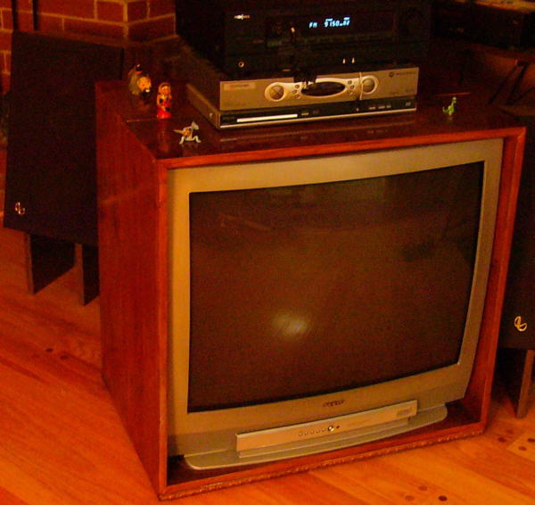
I bought the TV in March 2004 and constructed a custom console for it. It needed to swivel, so I put six wheels underneath (hidden by the moulding strip) in a fixed circle orientation.
There's also a center bolt-mounted pedestal slightly higher than the wheels to facilitate the rotation. After cutting, assembling, and staining I believe I used up the entire can of Minwax!
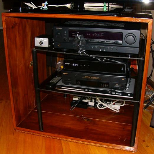
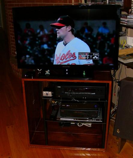
In August 2014 the CRT HDTV was 10 years old and I figured it was time to invest in a flat panel for its replacement. I had procrastinated mostly because I didn't want to deal with re-doing the wood console.
So I built a two-shelf interior (a Telcro II cabinet smoked plexiglas front cut in two with wooden dowels as legs) to hold the stereo and video equipment, and placed the TV on top.
Bird Feeders
(Also see my About Birdcam page)
Main Feeder: I went through a variety of feeders on the dogwood tree at the front of the house.
I started with a simple purchased one that looks like a birdhouse (in the center post feeder shot, below). The squirrels happily sat on it and finished its contents off.
I then tried a commercial "squirrel proof" one that just gave them a convenient cage to hold onto.
I tried blocking the treetrunk with surrounding sheet metal to prevent the squirrels from climbing up to the feeders. Had to keep expanding it until it actually worked, but it looked extremely unsightly.
Additionally, some brave squirrels climbed up adjacent trees out to overhanging limbs and attempted to drop down to the feeder. They sometimes made it and sometimes missed --
plummeting maybe 60 feet or so to the ground -- dazed, yet unfazed. I really didn't feel comfortable encouraging animal suicide, though. I abandoned the blocking tactic.
Then I started fashioning my own feeder construction attempts:




In March 2002 I built one (above, but less the top container and tubes) from the top of a cake server (upside down). I put a plastic container inside to keep the seeds at the periphery near the access holes.
Below the separation by another plastic container, there's a shelf made from a suspended ceiling light panel.
At first I had the feeder directly suspended by two chains (the seed cavity top is a plastic disc sold for isolating squirrels), but the squirrels just walked down the chain,
hooked a foot on the chain -- and leisurely served themselves by reaching to the feed holes. I added another plastic container to the top and covered the chains with clear cylinders (first and second photos above).
As seen in the second images above, they still managed the same feat. I put a taller container at the top (third shot, where I also changed the bottom container).
The squirrels still could jump to the tray, which was flimsy enough not to support their weight -- but I was afraid the panel would break. In fact, it did:

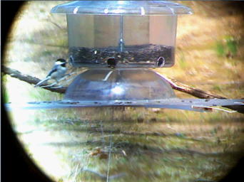

You can see this arrangement just gave the squirrels a convenient sitting place to eat. But I was almost there, the salad bowl needed to be attached to the seed cavity and free from the tray. I determined that the feeder requirements were: (1) there must be nothing for squirrels to grab or hold on to; (2) the top must be large enough to fully prevent them from reaching down; and (3) it should hold more seed to make it last longer between refills, because taking it down was cumbersome. So in September 2002 I designed an entirely new one out of plexiglas (acrylic plastic) from scratch:



The inverted pyramid container directs all of the seed to the bottom feed holes; is large enough to hold 25 pounds of birdseed (which lasts 4-8 weeks); and provides nothing to grasp. The tray is plexiglas, much stronger than the ceiling panel. I added clear moulding edges (with spring releases to flip down when squirrels jump to it) to trap fallen seed. The pulley/weight system is retained, but the separator (salad bowl) is attached to the top section and not the tray itself -- when the tray drops down, there's nothing to grab. Originally (above left) the roof was the same size as the bottom tray, but I modified it to provide an overhang on all sides to make it impossible to drop down onto the tray (two right photos). Initially the weight was a plastic container filled with counterbalancing rocks, but it was unsightly. The final configuration is at the right, filled with aquarium rocks and fake seaweed. I also suspended it with a double rope through pulleys on the tree branch, so I can hoist it up and down for refilling. The squirrels occasionally jump onto the tray, but they immediately fall off. Success! It has remained unchanged since the beginning of 2003, except I redid the roof with quarter-inch thickness material -- as it had to be strong enough to withstand the weight of a foot or more of snow.
Post Feeder: I also put some birdseed on a tray I quickly attached to the entrance post lamp.
At first I just attached it to the side of the post with wire, and of course the squirrels just walked right up the post and sat on the tray.
So I added some sheet metal to the sides and surrounding the post to prevent them from climbing up or grabbing on when jumping from the ground, etc. (left, 8/2003 shot):
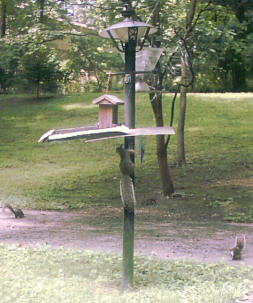
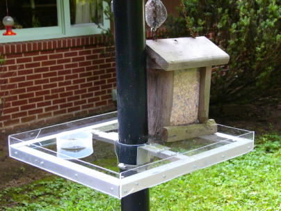

That was kind of ugly, so after my plexiglas experience with the main feeder, in 2004 I constructed a new post feeder that surrounded the post (center shot).
The squirrels couldn't simply climb over it, but still some enterprising ones managed to catapult themselves off the post and around to grab onto the short side.
I added some flat horizontal extensions on those sides with limited success. Then I came to the final solution: the long vertical extensions (right).
Now no more squirrels on the post feeder -- except when we get a few feet of snow, which puts the shelf within jumping distance from the new ground level.
Miscellaneous Electronics
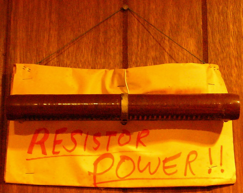
You needed a special sense of humor to appreciate this in the 1960's/1970's:
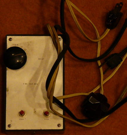
I built the timeout box at left circa 1970.
I think this is the schematic.
You power a radio from it, set the on period, and go to sleep. It'll shut down as desired. Nowadays all clockradios do this.
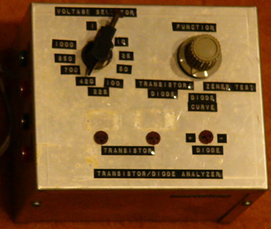
The Transistor/Diode Analyzer at right is from the 1970's. Connect an oscilloscope to it and it generates voltage/current curves.
I bought lots of (unknown) "surplus" semiconductors from sources such as Poly Paks for pennies and measured the parameters to see what I had.
It's Academic

We were buying key systems from T.I.E. in Connecticut -- the KSU's (main phone box) had to be put together with wirewrap dependent upon the installation's requirements, but the circuit boards were ready-to-go. Initially my job was to build and then design simple modifications to the standard T.I.E. gear. This included an interface to permit callers on hold to hear a radio station or a tape deck instead of the built-in mechanical chime; ring a bell (a really loud bell, enough to wake up the dead) for warehouse operation when the phone rang; conference units, etc. Later I tried my hand at designing speakerphone circuitry, with a modicum of success, but not really good enough for commercial usage. Here are my various schematics.
The brothers who owned the company seemed to have some trouble differentiating real business matters
As a second-year EE student, I was very happy to be designing circuits with operational amplifiers (which I had just learned about from Prof. Westgate's class) and I probably wasted unnecessary time with all that.
But they didn't care (as if they even knew), because they were paying me so little (but still a few pennies more than I had been getting sweeping floors!).
I had digested in detail every single T.I.E. schematic until I understood precisely how the phone systems worked.
Which really wasn't required to build, install, or maintain them.
 The owners (two brothers from New York) supposedly acknowledged my capability by making me
I remember one particularly humorous maintenance call: #2 brother had gone to one of our customers and tried to get him to pay his bill. He wasn't having much luck, so he went over to the KSU and started randomly pulling out circuit boards. Of course, the phones started going dead all around the office. Needless to say, the tactic worked and the customer immediately wrote out a check and begged to get his phone system back up. The #2 brother might have been a good salesman, but he had no technical knowledge whatsoever. And he began plugging cards back in without considering that in fact they are supposed to go into particular slots. So he burned out the whole thing. That was a service call I took, quite happy to simultaneously be correcting a boss' ineptitude while getting the higher salary!
Later on, as the company failed (the brothers treated it more as a personal playground rather than a serious business) and the workers gradually departed (which tends to happen when paychecks bounce), I ended up doing all of the company's maintenance -- and they did in fact pay me the higher rate all of the time. As the very last employee (I myself had to resort to some trickery to get my final pay from brother #2), I carried a beeper with me to class (in silent mode) and checked in on service calls in between lectures. This was before beepers became commonplace devices for drug dealers and tethered children (long predating cellphones). When that experience was over, I vowed never again. And I never did.
In a strange Twilight Zone type of quirk, years later when I ended up at Telesaver, they moved into the exact same office space that Sonaphone had a dozen years earlier inhabited: 20 Gwynns Mill Ct.
There was no connection whatsoever between the two businesses (other than me, and I had nothing at all to do with location selection).
I had a bunch of the leftover Sonaphone stick-on aluminum labels which I made various uses of, including small heatsinks. I thought it was funny that there were two misprintings on them:
the city name, plus we were the only U.S. company with an 11-digit phone number!
I built two versions of this automobile alarm system:
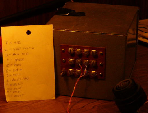
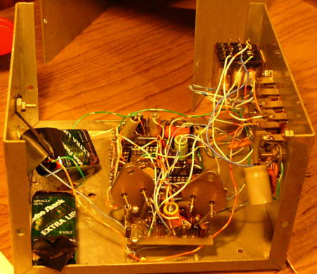
The
first was TTL (probably in 1974, the schematic is undated) -- it drew more quiescent power than one would like for a continuous drain on the car battery, and was somewhat susceptible to transients causing false alarms.
The second version was CMOS (February 1975),
which solved those problems. They both functioned identically. The alarm monitored the dome lamp; once a door (or hood or trunk switch) was activated,
the user had to close and re-open the door within five seconds to disable it. There was an under-dash enable/disable toggle switch. My system required no special keys and it wasn't
necessary to go to one particular spot on the car to disarm, as was customary at the time. When the alarm tripped, it honked the horn (on/off), enabled a Sonalert beeper (in
case the thief unplugged the horn), and disabled the starter circuit (in case the robber wasn't worried about drawing attention). I knew better than to interrupt the ignition circuit (:>).
After a false alarm burned out my car horn, I added a two minute timeout on the horn activation. One 9V battery was in case the thief cut the battery lead, it would still activate
the Sonalert; the second 9V battery boosted the voltage to the Sonalert to make it louder. The alarm was on my 1972 Chevy Nova and then my 1981 Toyota Tercel. I retired it when I
bought a 1995 Infiniti, which has a built-in alarm. In service 20 years, not bad!
Every digital dabbler must have a Logic Probe:
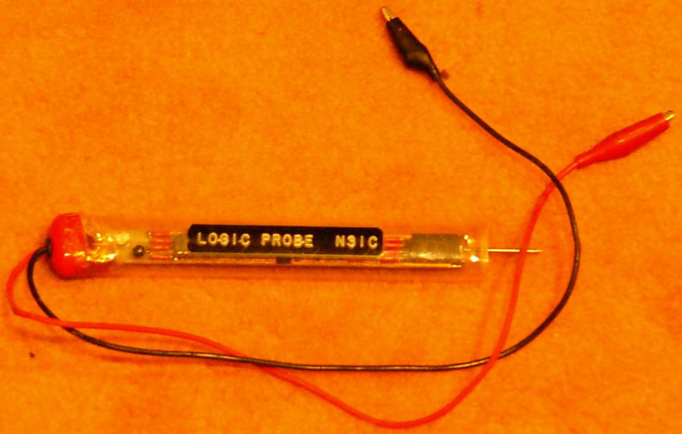
This circuit was in September 1975 Popular Electronics. The only tricky part was making it small enough to fit into a toothbrush tube.
The 7-segment display shows H (high), L (low), P (pulse), or O (open circuit). This is no big deal now, they all do that.
But back in the 1970's most probes just showed High or Low. Had to etch a small circuit board from the magazine artwork.
Here's the article.
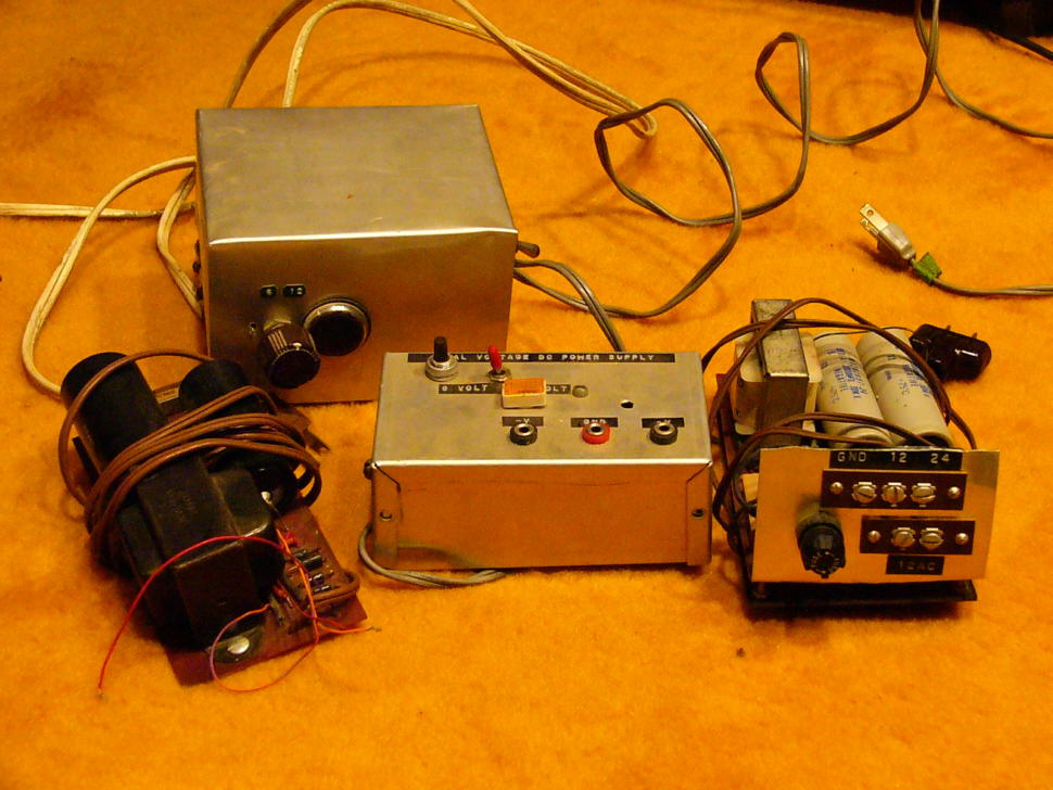
You can never build too many power supplies:
Beat the Reaper


At the JHU Amateur Radio Club, those rigs cost a lot of money. So we earned extra cash at the annual Spring Fair.
All of those fairs run together in my memory, but these pics are probably from the 1974-1976 time period.
We had a prime spot at the top of the stairs between the Gilman and lower quads (center pic looking south towards Shriver Hall).
Steve Fick WA3EVY (now N3TE) came up with his "Beat the Reaper" game of skill. We built this very complicated (haha) electronic challenge for fairgoers.
Can't find the schematic.
You had to navigate the metal loop from one post to the other without touching the bent copper tubing.
One false touch and a "lose" gruff buzz latched and ended your attempt.
If you make it all the way across and touch the end braid, you "win" and latch a nice pitched tone sound.
Of course, we held the power on/off button in our
Steve writes: I remember a very raspy buzzer, with a 12" diameter 35mm film can as sounding board, which was triggered on timeout or when the wand hit the wire.
The control circuit was built around a thyratron (2D21) controller from my junk box.
I remember a length of RG-8 shield, at the end of the wire and insulated from it, which the customer touched to trigger a success indicator. However, I don't remember what that indicator was.
It might have been a Mallory Sonalert (I agree). I can't find the schematic either.
I remember visiting the shack in 1985, shortly before it was leveled to make way for the sculpture garden.
The Reaper tubing and poles were still there. The club was inactive, and the place was in tatters. All the gear within about 2 feet of the floor was ruined, though, by a flood.
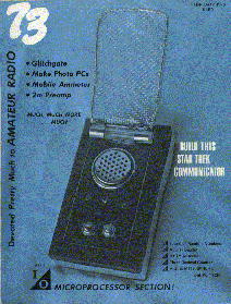
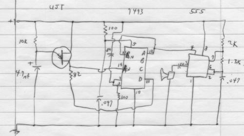 Marc Leavey WA3AJR was a real (original) Trekkie, and he wanted a Communicator.
I designed a circuit for him which mimicked the sound the TV show's devices made when flipped open.
At the right is the initial version of that circuit. He constructed a pretty good imitation of the icon and built in the circuit. Cool (well, back then it was! Remember, this was before cellphones.).
He
published an article on it in the February 1976 issue of 73 Magazine. It was made into the lead magazine article and garnered the cover (at left)!
In October 1974 while an undergraduate I did a consulting job for Barry Hirschowitz to design and construct some type of medical device.
I can't remember exactly what it was for, but think that it measured small skin voltages.
I might have been given schematics of a commercial device based on vacuum tubes that performed a similar function.
It was essentially a very high input impedance voltmeter, and drove a large analog meter
Replicating Digital Synthesizer
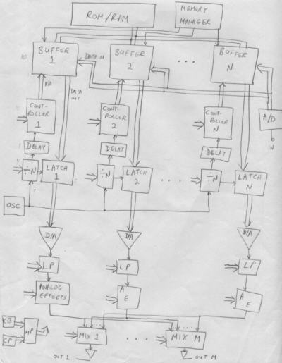 In 1975 fellow undergraduate student Eugene Mauro came to me with a proposal.
Music synthesizers of the day were analog devices which created interesting but clearly artificial sounds.
His idea was to use nascent computer technology to record and play back real musical instruments at different rates to produce a new kind of music synthesizer.
He was a musician, and had taken some electrical engineering courses, but knew that he couldn't design it himself.
Eugene's plan was to write up design details, build a prototype device, and obtain a patent for it.
He paid me some money (I wouldn't do the work purely on speculation), and we were to share in the profits when they came rolling in.
He had a patent attorney working with my writings, but the predictable happened: he ran out of money getting the legal work done.
Let alone to have enough to actually build the prototype, which we estimated would cost thousands of dollars.
The design was fairly large, consisting of multiple microprocessors (interesting that I selected the COSMAC processor for it) --
but I had (and still have) no doubt that we could have built it and that it would have worked.
He had little choice but to abandon the project.
To this day, when I pass by the dozens of inexpensive Casio synthesizers in the electronics stores -- which are simply cheaper modern-day implementations of his Replicating Digital Synthesizer -- I cannot help but think of Eugene and lament that he never got any credit, let alone millions of dollars, for this. He had a music store in Waverly for a while. I ran into him maybe ten years later there where he had happily recently obtained some professional recording studio equipment.
Here are my description and design documents.
MET-1
I designed an interface system for Maryland Electrical Testing (MET) which was delivered in September 1977. They were conducting an extensive powerline measurement study, I believe for the Army in Virginia. They had purchased many magnetic tape recorder units produced specifically to log AC voltage, current, and phase for that purpose: these recorders moved very slowly -- I think each tape cartridge lasted around a month. The recorder manufacturer also sold a reader device which would play the tapes back (at high speed) which connected in some way to a computer system for analysis. Which is exactly what MET needed. But it was extremely expensive. They thought "what's the difference between a tape recorder and a tape player?" The electronics! They figured they could modify one of the inexpensive recording units to instead play back the tapes. And they contracted this then grad student to design and build them the electronics for it (ostensibly for a lot less money than the commercially available reader).
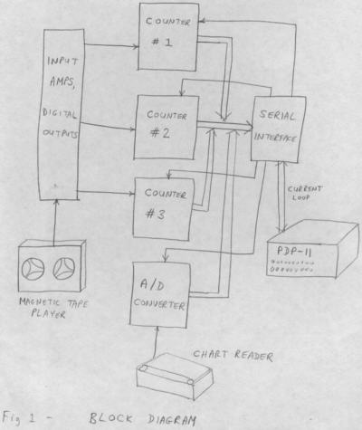 This was an interesting project. The tape recorder had a capstan to keep the record speed fixed at a slow rate; on their modified unit they had removed the capstan.
This let the tape cartridge spin as fast as the drive motor could spin -- which was quite fast, and moreover, not at a fixed speed as the tape wound from one side of the cartridge to the other.
The record electronics was of course bypassed and my circuitry hooked directly to the tape track head coils.
I didn't really know what the signal level coming off of the head would be, but a measurement showed that it was in the microvolt range. Seemed kind of low (maybe in retrospect), but I designed the analog front end to amplify it a gazillion, used differential mode, and employed shielded wiring because that much amplification was sure to run into noise and pickup problems. It worked, but not as well as we'd prefer -- there were read errors after signal discrimination (NRZ decoding). One of their guys scratched his head and thought "Shouldn't the signal level be higher than we're seeing?" He looked a little more closely at the unit, and guess what he found? There was a permanent magnet hidden in front of the tape head to erase the tape! Made perfect sense, this box was sold as a recording device! But we were using it to play back the tapes, and every time we ran a cartridge through it, the tape was being erased more deeply (that might have been the big clue). I had so much signal gain in my circuitry that it was (partially successfully) reading the residual signal left behind after erasure. (Why couldn't the NSA use this same technique to read the erased 18.5 minutes of Nixon's Watergate tapes?) He removed the magnet and the signals were now in the millivolt range. I trivially reduced the gain in my front end, and presto, the tapes decoded perfectly reliably.
This project was a little after my MAXI micro endeavor, and I used some of the same techniques: 44-pin edge connector Radio Shack prototype wiring boards and card cage. I even used an Intel 8224 clock generator chip to drive the UART -- I knew it was overkill, and the 8224 ran notoriously hot -- but it certainly could do the task without a care on my part, and as a bonus it included the power-on reset circuit I also needed. This was not a microprocessor-based project, it was pure hardware. It had to pick up the signal and clock data off of the tape head, decode the NRZ pulses, and transfer the information to MET's PDP-11 minicomputer. I used a standard current loop serial interface to the PDP-11, but knew that the computer and interface would not be fast enough to collect individual pulse info. So I designed in hardware counters which the computer could poll periodically to retrieve the information. My undergraduate PDP-11 experience came in handy for this project even though I didn't really have to directly deal with that end of the system. After the magnet episode, it worked great without any problems. Almost as an afterthought, they wanted to be able to use the same device to input paper chart power data as well. They had constructed a tablet type of gizmo that let them put a printed chart on it and have a clerk meticulously move a stylus to various points on the graph; it was attached to a potentiometer. So my box had a mode to read the pot voltage with an analog-to-digital converter (ADC) and transfer the data to the PDP-11 whenever the operator pushed a sample button. Sounds crude, but this was 1977 and it did everything MET wanted.
Sometimes when you don't hear back from a customer after a while you wonder if equipment is even being used.
But I ran into them a number of years later, and learned that they used my MET-1 interface for quite some time. Nice to know!
Before specialized digital chips came out, it took a lot of circuitry to create the Pong video game:
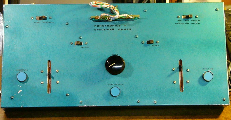
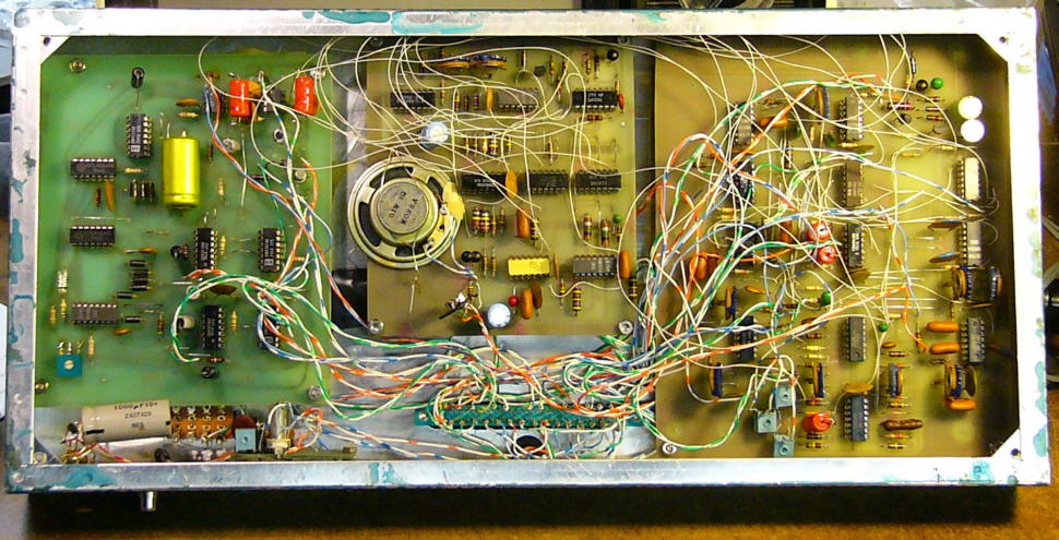
I combined two separate games -- Pong and Spacewar -- into one box. The edge card connector was double-sided; you plugged the cable in one way or the other to select which game.
These CMOS circuits were in the magazines. I added a channel 3 modulator so you didn't need a video input (which wasn't common in the 1970's) on the TV.
I was very impressed with these games, you could even play the machine! Until shortly thereafter when single-chip solutions came out, which put these games to shame (:<).
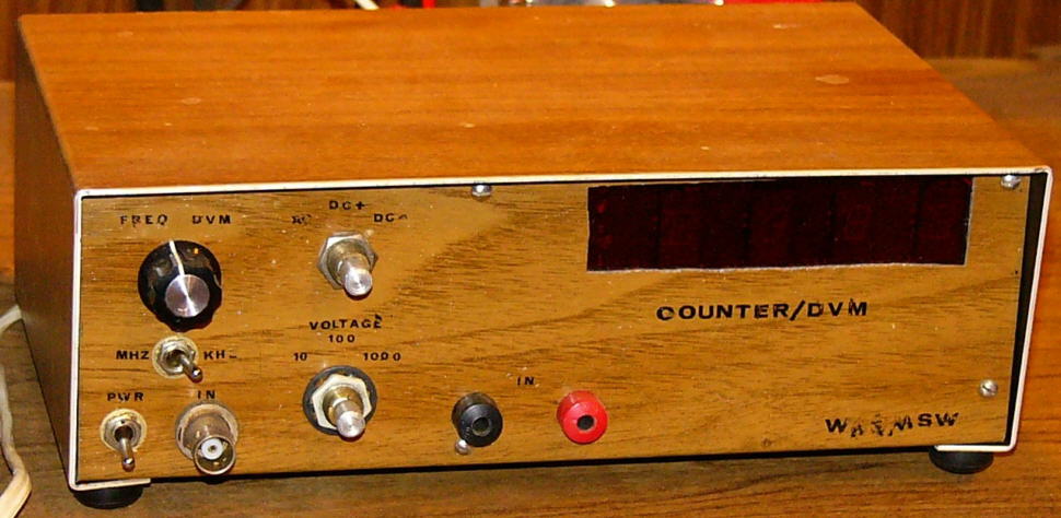
Frequency Counter/Digital Voltmeter from around 1976?
Every mad scientist's lair must have a Jacob's Ladder:
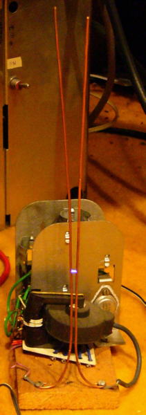
I bought the circuit intact from one of the hobbyist parts suppliers in the 1980's, it's just a transistorized flyback high voltage circuit.
Powered from 12 VDC.
I have a looseleaf binder filled with many other schematics I had designed. I just don't have the circuitry anymore, or can't quite remember what it was exactly for.
Maybe that's why I take it out on my students now, forcing them to write better documentation!
In 1981 the first DTMF decoder IC's had come out, so I designed this Message Converter as an entry in a contest:
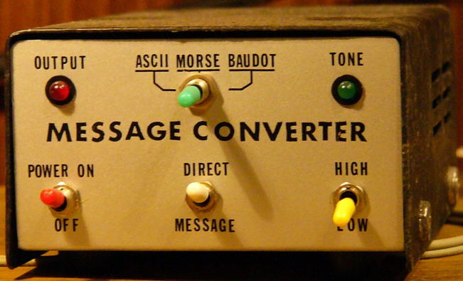



It used an 8748 microcontroller (actually an 8035/2716 combination, which was much cheaper at the time) and the DTMF chip to listen to tones on the phone line and convert them into ASCII, Baudot (typical TDD terminal then), or Morse code (LED illumination) formats.
(To permit the deaf to use the phone.) Each letter used two depressions, the first the button with the desired letter, followed by 1, 2 or 3 to designate which letter.
For example, 23 supplies "C" because the "2" button has "ABC" on it.
That's my MAXI micro Term, TV monitor, and two telephones to demonstrate the system at the show exhibition in DC.
When my wooden road sign deteriorated amidst occasional repair, I replaced it with a more modern version in October 2003:


It has 198 line powered LED's (draws 14 continuous watts). The colors don't show up too well in the photos -- the name is green, number yellow, and arrow red.
It is visible even in daylight, and deliverymen appreciate it!
Built onto two aluminum rack panels (front/back).
I built a Theremin for my friend Larry Kruger as a birthday present in February 2005:
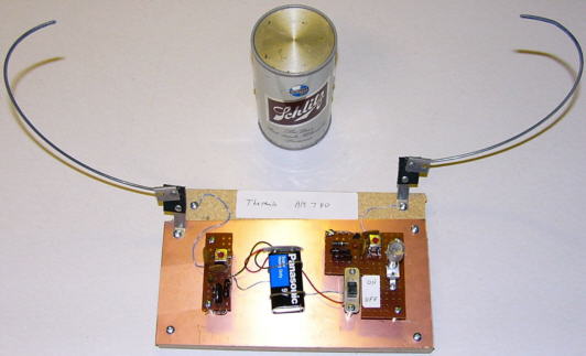
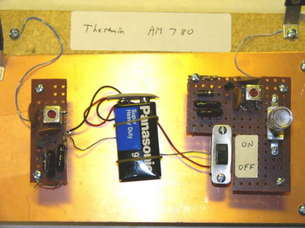
The old-fashioned device has two RF oscillators, one fixed and the other nearly zero-beat to the first with the frequency trimmed by nearby body capacitance.
You wave your hands around it and the frequency difference comes out as a variable audio tone on an AM radio (my beer can radio above).
Very popular device to generate eerie sounds for old science fiction movies!

Wire Recorder
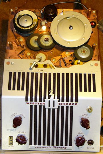
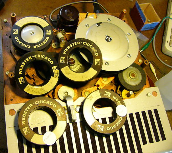
In February 2012, my friend Russ N3YI brought over a wire recorder that had been in his family since before he was born. Apparently these were predominant in the late 1940's and early 1950's; after that reel-to-reel tape recorders took over. His unit was a Webster-Chicago model 180. Here is some literature on it that was with the box. (I am amused at the drawing on page 4 of the lady in heels easily carrying the "portable" 27-pound unit. Compare that to a two pound MacBook Air!)
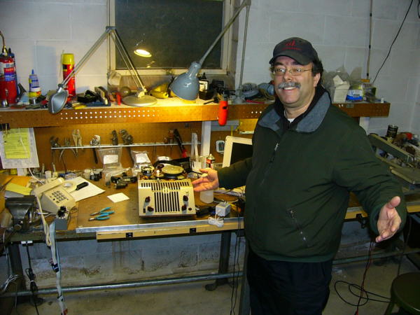 The unit had been passed down to him, and since he was a kid he had wondered what the recordings that were on the spools of wire sounded like.
He had already had the AC power cord repaired, but nothing happened when it was turned on. I found the power fuse and it looked like it had disintegrated; so we replaced it and turned the power on.
The tube filaments lit up -- after about 20-30 seconds, one of the plates was glowing red. Then the new fuse blew. I knew that the most likely failure mode for this type of gear not turned on in probably 50 or 60 years was the electrolytic filter capacitor.
So I actually had slowly ramped the line voltage up with a variac rather than directly powering from 120VAC. I'm guessing that replacing that cap will restore the box to operational order, but didn't bother with that.
Our goal was simply to retrieve the audio recordings for Russ (at right).
I pulled all of the tubes to prevent the (again replaced) fuse from blowing. The good news was that the motor (there is only one) worked. After some cleaning with alcohol and judicious lubrication I could make it go forward to play and reverse to rewind. It still took some finger action on the mechanism to get it going in either direction. The rubber mountings had deteriorated and in some cases turned to dust. The wire broke a few times in the process of getting the mechanism to do its job. It's kind of interesting that there is a mechanical part which moves the head up and down as the wire winds onto either the supply or takeup spool. This evenly spreads the wire onto the spool much like a sewing machine, and prevents bunching. I also thought it interesting that there is no capstan -- which on reel-to-reel and cassette decks keeps the tape velocity constant as the diameter of the takeup reel increases throughout the play time. This design simply used a large diameter takeup spool, so even when it is filled from the supply spool its diameter isn't much greater than at the start. The motor speed and idle wheel reductions set the transport speed.
With the tubes removed, we had no active electronics. But we didn't need no stinkin' tubes! I attached the leads from the head to the input of a (transistorized) audio amplifier (in between the two laptops in the picture below). We threaded the wire through the (playback in this mode) head and the takeup reel and got the wire moving. We could hear the audio from the past emanating from the amp's speaker! The rest would be a cakewalk.
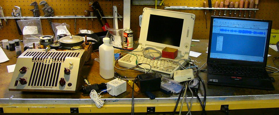
I tried feeding the head signal directly to the microphone input on the laptop, but there wasn't sufficient gain. So I connected the head to the input of the transistor amplifier and the amp's output speaker jack to the laptop's line-in jack. With Audacity I could record the session and edit it afterwards. There were sections of the wire ("tape") that had great audio levels and others that were much lower. Some were simply people talking too far away from the microphone, but on other sections I think that someone pushed the record button over top of the previous recording and mostly erased the former data. I selectively edited portions and amplified them (a lot) to try to bring the sound up to a listenable level. Of course that boosts the noise level quite high. Another problem is that I live too close to WCAO-AM (they moved their transmission towers to the neighborhood after I moved in!). So in the sections of the recordings where I amplified it a lot there is a residual background of the local radio station. Oh, well.
In the end, I made up audio CD's and MP3's for Russ of five recordings: Sondra's sweet 16 birthday party (his Mom); Rosie's birthday party from February 29, 1952 (Russ' great-grandmother whom he is named for); the Kaufmans' 25th anniversary party (Russ' grandparents); a recording off of Philadelphia's WPGM fm radio station (I think those are the call letters, it is a bit hard to clearly make out); and a sales pitch from Slenderella (the voice is a British woman which makes more sense when I see that the company is in the U.K.). Here is that last recording. Here are all of the recordings. You will need to get the unzip password from for those.
It was a fun little project which reminded me of the vacuum tube days and the more formal manner people behaved in radio-like interviews in the 1950's.
Car Radio
I had noticed some detritus in the trunk of my 1995 Infiniti. Further inspection revealed that the rear speakers had deteriorated -- the cones were now isolated from the frame, suspended solely by the voicecoils. Recalling how easy it was to replace speakers in 1970's era cars, I looked to swap them out. But I couldn't figure out how to remove them! They were clearly bolted in from above but there were no screws on top to remove the grills in order to access the speaker mounting screws. I concluded that it would be necessary to actually remove the rear deck below the back window. This seemed drastically crazy, but a web search provided instructions (which didn't turn out to be precisely correct) indicating that I wasn't crazy, that deck indeed had to be removed. Didn't want to leave the car disassembled too long, so I bought replacement speakers before removing the originals and attacking the job. These are two-ohm units, and most of the ones available are four-ohms. Ironically, I found and purchased a pair of Infinity speakers for my Infiniti car. It was a bit of a job removing the top deck, but it all worked out. Got this done in March 2012 and now the bass response has returned. I guess these speakers will last the remaining lifetime of the car.
 With the speaker problem fixed, I wanted to address an issue that had been gnawing at me for a while: playing MP3's in the car.
At first I had tried a Belkin FM transmitter to let an MP3 player broadcast to the car radio. It appeared to have a very low output power, because no matter what frequency I selected it seemed to heterodyne with broadcast stations as I traveled. It was too aggravating. Plus I was using the cigarette lighter socket to power it and it was more cumbersome than I'd prefer to hookup and disconnect.
I had settled on using a standalone audio amplifier (abandoning the car radio altogether) -- the same one shown above in the Wire Recorder episode. Powered also through the cigarette lighter socket, it worked okay. But it still was a cumbersome connection and of course the sound was not nearly as loud as the car radio would be.
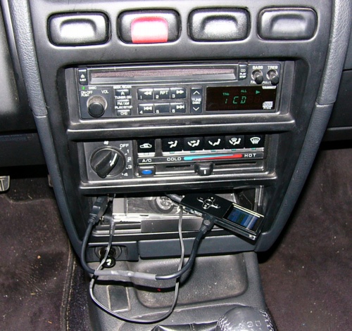
I was determined to establish a direct connection between the MP3 player and the radio's internal audio amplifier. After figuring out how to remove the surrounding dashboard cover (that houses the four accessory switches at the top of the photo) it wasn't too hard to remove the radio itself. I took the top and bottom coverplates off of the radio. Still thinking with a 70's attitude, for some reason I expected to see a stereo volume control potentiometer which would have been trivial to interrupt to divert the audio input to an external jack. But of course I knew that this radio was all digital -- the volume control is an optical encoder that drives a microcontroller. As an integrated unit I wasn't sure how I could find a place to cut the audio path. I was stymied trying to remove the circuit boards anyway: I didn't readily see how to release them (without a service book); I was afraid that I would pry something that wasn't intended to be pried and break a perfectly good radio.
There were two unused connectors on the rear of the radio. I recalled that this model had an option for a separate CD changer unit that mounts below the heating/cooling control section. There is a button on the radio to select this sound source (which did nothing at all without the changer installed). I became obsessed with using this audio path for an external MP3 player. Clearly this is the preferred method: all I should have to do is convince the radio that an external jack is a CD changer. I could connect a stereo audio input jack to the radio connectors and be done! I failed to get any specifications on the radio interface, even with the exact model number, so I attempted to reverse engineer it. How hard could that be? The radio connected to the car wiring through two plugs which were more complicated than the older simpler ones I was familiar with (power, ground, left/right speakers). I figured it would be easier to work with it in the car instead of running it on the workbench. So I made up a cable to connect to a DIN and some other type of jack on the radio, re-installed the radio and probed the signal lines with my VOM (actually DVM). There has to be a way that the external changer tells the radio that it's there. I guessed that it might ground one of those pins, so I carefully grounded each (through a resistor in case I was wrong). Pushing the radio button each time still did nothing. So I guessed that maybe a pin needed +12v instead of a ground for that purpose. Still nothing. Then thought that maybe the micro sampled those sigs on powerup; so I tried the ground and +12 on each pin (13 of them) powering down/up. Still nothing. I dragged an oscilloscope to the garage and looked at each pin while activating the radio button, looking for a pulse or something. Nada. I put a signal generator onto each pin (through an isolating cap) and found that I could drive the left and right audio paths (superimposed on the radio or CD playing). But the MP3 player's audio output on those same pins accomplished nothing -- the sig gen must have been overpowering internal circuitry. Anyway I still had the other audio source running. It killed me, but after spending a couple of days on this I had to admit defeat. I know this is the way to go, but without the radio or changer specs I could not make use of this method!!!
Back to Plan A (interrupt the audio path inside the radio somewhere and attach an external jack). Pulled the radio out and removed the covers. After about a half an hour or so I managed to remove an auxiliary board which houses the balance, fader, bass, and treble controls. The audio path has to go through here, right? Failed to identify any discernable signals. After about another half an hour or so I manage to remove the main circuit board. I was a bit terrified with this: there are a couple of flat cable connectors, I was flying blind, and feared I would break something or not be able to re-assemble properly. This radio has a built-in CD player (one disc as opposed to the 6-disc external changer) and I thought that there would be a separate CD player circuit board which had to attach to the main board. There just had to be a stereo audio path between the two! My guess was correct: there was a flat cable between the two boards with about 15 or 16 lines. By this time I had gotten the radio operating on the workbench. My plan was to interrupt the CD audio path, so I would have to play a CD while listening to MP3's. I put the boards back into the radio and good news, it still functioned. But now I had to find the left and right audio pins on the interconnecting flat cable. To get to the board pins the radio had to be upside down while playing a CD: it made a scraping sound but mostly managed to play with the anti-gravity positioning. Tadah! Found the two audio paths. Next job is to interrupt them. Removed the board again. It is a combined surface mount/through hole configuration. After some work I identified two traces I could cut to accomplish the task. With a 4-conductor + ground shield cable I routed the two audio paths through the cable to a standard stereo miniature jack with internal normally closed contacts. Routing the CD-audio through the cable/jack was not as ideal as the failed Plan B (CD changer one-way audio input) but should work fine. Reassemble everything, try with MP3 player, and it all works great! Lucky for me the audio levels were compatible as is.
It would be nice if the MP3 player's internal battery charge level were not an issue in the car. On a roll, I wanted to put a charging jack near the car radio. So I put in a 5 volt linear regulator and attached its output to a standard USB socket. I mounted it directly above the cigarette lighter but for the life of me I couldn't get to its wiring to power the regulator! Just bridged a wire onto the +12v pin on the radio connector to feed it. I could now use a standard USB cable to the MP3 player to charge it. (Two days later in the dollar store I saw a dual USB converter that plugs into the cigarette lighter socket that accomplishes the same thing -- but it is bulky and awkward compared to the jack I installed.) As a finishing touch, I made up a 6" USB cable and a 12" audio patch cable to avoid a bunch of unnecessary cabling in the cramped space.
The final configuration is in the photo above. The external audio input jack and USB charging socket are just above the cigarette lighter. To play a CD I just have to unplug the audio cable from the external input jack. While I had the dashboard open I added a small piece of angle stock (painted black) to the bottom of the tray where I usually put the empty CD case for the loaded disc -- occasionally it would fall out when accelerating (nice after 17 years).
One MP3 player I have will charge while it plays if the two USB data lines are shorted to ground; another one won't charge unless the data lines are open! (it still doesn't display that it is charging, but it is). So I added a
Chimney

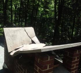

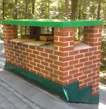
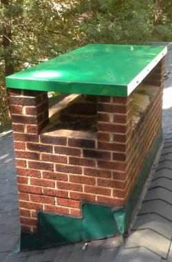
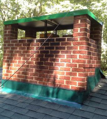
On June 24, 2015 I noticed that the top of my chimney had fractured! At first I thought that a tree branch had fallen onto it, but it had simply collapsed of its own weight. I was kind of perplexed as to how to replace it. I found that I could purchase a Pennsylvania bluestone piece for around $750, but didn't investigate how to get it up there. Likely it would require a crane and I figured that would cost lots of bucks. I ended up having a Chase Cover custom made, but first I had to get the old pieces off of the roof. The roof shingles had accumulated moss and had generally deteriorated underneath low-lying tree branches since I had the roof replaced. I hired a power washing company to clean the roof, gutters, and a few other things around the house. Before they started, the three of us managed to lift the slate pieces off of the chimney and heave-ho them into the back yard:



The way the big piece landed reminded me of the Monolith in 2001 A Space Odyssey! Taking the lazy way out, I rearranged the various pieces to add to the rear walkway. The new cover was relatively weak sheet metal and I feared that just attaching it to the four brick posts would not self-support snow accumulation. Pondering the problem, I came up with a steel angle bracket solution:
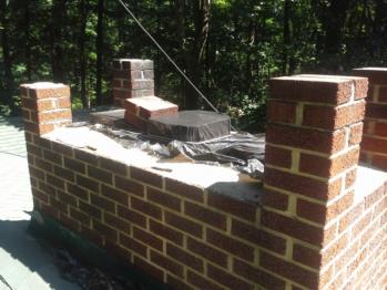
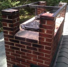
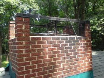
I first had to reglue two pieces of dislodged bricks. At first I was going to drill and put masonry screws into the brick, but I haven't had good luck with that in the past. So I wimped out and devised a metal strap method that tightened around each brick post and the center chimney stack. The angle stock was quite strong -- placing center support down to the chimney base was probably unnecessary. After cutting and before attaching, I painted all of the hardware flat black before assembly on the roof.

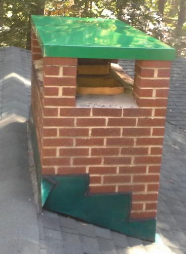
On the ground I painted the underside of the cover flat black and the top and outside skirt meadow green. After drilling holes and with more nuts and bolts, the job was finally complete on August 22:

Digitizing Music
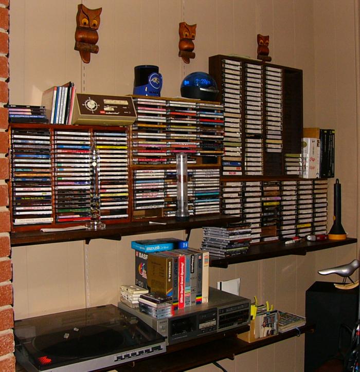 A lifetime of music collection is stored on CD's, cassette tapes, vinyl LP's, and 45's (at least I don't have any 78's or 8-tracks!).
My new car doesn't have a CD player (and of course not a cassette deck), so that prompted this project.
First, there are so many things counter to this project that I am sure the modern reader will say "Why Bother?" doing all of this.
For one thing, the car has internet radio in addition to broadcast radio, so there really is no need to supply one's own media.
More significantly, the concept of owning music is so old-fashioned. Why not just subscribe to Pandora, Spotify, or any of the countless music streaming services?
Nothing wrong with that, but I just think it is neat to be able to also have one's own personal actual physical archive.
I realized that conversion would take quite a while to complete, but still the thought of it all was intriguing.
So in the Summer of 2015 I embarked on this music digitization project (and had it completed in September). The easy part first: CD's. I used FreeRip to rip the tracks off all the CD's. This is mostly painless, as the program uses an online CD database to populate the album name, artist, track titles, and various tags automatically. Some editing is necessary, especially for compilation albums which have various contributing artists. I've also found that the database must have used human entry at some point because sometimes there are spelling errors or typos. But it takes about five minutes to process a disc, so I stayed at the computer while going through mail or reading the newspaper so I could begin and end the ripping process for each, and inserting and removing them. I decided to store everything in 192 kbps fixed MP3 format -- I think that this is high enough quality so that I will never observe anything different from a standard CD, and is ubiquitous enough so that any device should be able to play it.
Next, the cassettes. There was no way around the fact that realtime analog playback and recording was required. I still have the cassette deck that they were all recorded on originally, it is a part of my sound system. I also had years ago run shielded audio cable between the living room housing the audio gear and the office with the desktop computer. (Mostly used to record off-the-air shows long ago.) I had isolated each channel with 600 ohm: 600 ohm transformers to minimize extraneous hum pickup, and that worked pretty well. So I began the laborious process of the analog recordings. I used Audacity along with the computer's sound card input. I temporarily stored each 45-minute piece (I mostly had recorded an album on each side of a C-90 tape) as a raw file in CD quality (44,100 samples/second, 16-bit stereo) form. Most of them were recorded as I watched Orioles games, starting/stopping and flipping the tapes every 45 minutes. Usually I use the stereo system to listen to the television audio, but I sacrificed the sound quality of the play-by-play announcers (sorry Jim Palmer and Mike Bordick!) and just used the TV's internal speakers for the games so that I could use the stereo for the playback process.
The day after recording several tapes I processed them. This was more time consuming than for the CD's. I used Audacity to isolate the tracks and save each one in raw CD format. Then I used FreeRip to do the mp3 conversion as with the CD's. However, this time I didn't have the automatic data population capability. I manually searched FreeDB for the particular album, then copied/pasted the album, artist, and track names along with album year and genre. I had to manually type in the track numbers individually. Having the track times listed in FreeDB made it easier to isolate the tracks from one another when cutting them out in Audacity as well. This process ended up taking about fifteen minutes for each album (half of a C-90 tape).
Lastly, on to the records. I don't have that many of these ancient recording repositories. Same process as the cassettes, except that I had to flip them every 20-25 minutes. First I had to repair my turntable (not for the first time, either). It is a linear tracking Sony, and the drive belt between a reversible DC motor and the arm movement deteriorates every so often. Couldn't find any suitable replacements this time around, but with judicious searching found a rubber band that works well enough. The neat thing about the linear tracking method is that precision is not required for this piece, it gets the arm into the vicinity with activation and feedback to move it along the width of the record. Rubber bands don't last as long as proper rubber belts, but they don't cost anything and when will I use the turntable again after this project?
The farther I got along in the analog recording part of the process, the better I got with the processing. I did not want to spend too much time on each piece or it would take forever and possibly cause me to abandon the whole project. But there were a few things I fixed along the way. My cassette deck had had an intermittent problem from way back: occasionally when recording it would interject some oscillations on one track. I know exactly why: a relay that switches the head coil between record and playback modes sometimes would not make a good closure, open-circuiting it leading to instability. I was going to replace the relay way back when but deemed it too much work to get at it for its rare occurrence. I had found that it only reared its ugly head when the deck was cold, so I had developed the practice of putting the deck into record mode for a while before actually making the recordings -- that mostly alleviated the problem. Still, some bad recordings resulted. Generally that amounted to a few bursts of less than a second for the first few minutes of an album on tape. But now that the music was digitized, an easy fix! When I noticed it (I did not actually listen to the tracks while going through them) mostly by seeing the waveform in Audacity I simply copied the audio from the good track over top of the bad track. So an outlandish buzz got replaced with a monaural section -- pretty much unnoticeable.
I also became more particular over the levels as I went along. If the right and left tracks were within a dB or so when visually inspecting the waveforms, I left them alone. If they appeared too different, I somewhat equalized the volume levels between the two tracks in Audacity. I realize that this is a tradeoff between technical recording deficiencies and intentional artistic choices -- but I am pretty sure that I wasn't overriding the musician's intention. I found that the problem of vastly different channel volumes was most evident in prerecorded cassette tapes. I vaguely remember from decades ago that it was well known that these were of poor quality, which was ridiculous!
Deciding how to manipulate the volume was also more of an art than a science. With analog recordings there are always some instances of quick clicks, etc. that exceed the volume of the actual music. Audacity provides a built-in amplitude adjuster such that it avoids limiting, but I used my judgement to sometimes let it clip when the clipping seemed to be only for artifacts and not the music's true dynamic range.
I also made use of Audacity's built-in click and pop removal tool for the recordings from records I had on cassette, and of course the records themselves. I didn't bother with experimenting with the parameters; I figured I could probably find some settings that would remove more of them but sacrifice the actual sound quality in the process. So I just accepted the default values, assuming that they were already configured to do a decent removal without deteriorating the data noticeably. The tool minimized them, though certainly not removing them. On the poorer recordings, it was actually not that easy to discern the boundaries between tracks when the record noise masked the silent interval; after the removal tool it was a lot easier to segment the raw data.
At the beginning of this project I had made the decision not to triage between music that I liked and did not. I figured that if I inserted opinion into the process it probably would make it take much longer, and then there is always the possibility that I would later regret it. It was simpler and faster to just digitize whatever I had. As a result, in addition to having music I do not care for at all, I certainly have some selections two or three times (from an original album and again in a best-of compilation, for example).
The result:

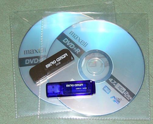
As best as I can tabulate, I digitized 176 CD's, 151 cassettes (mostly two albums each), and 33 records.
29.8 GB in total. My initial estimate was that it would fit on a 32 GB flash drive, but it wouldn't quite fit (when is a GB not a GB -- when it is counted differently because 2^10 <> 10^3, etc.). So I had to go buy a 64 GB flash drive after starting with 32. I had expected to put them on DVD's as well (and still might for safekeeping), to enable playback with my DVD player. I had also contemplated putting a laptop in the entertainment center for playback purposes (and still might do that, too). But then I discovered / remembered? that my television (whose audio output is an input to the stereo receiver) has a built-in USB input that can be used to play MP3's! So that is simpler. I can use the TV and its remote control to navigate through my entire music collection and play what I feel like. Of course I also put a flash drive in the car for playback.
After the project's conclusion I bought new tower speakers and a sub-woofer to replace my 32-year old Infinity speakers.
MediaMonkey reports that my digital collection consists of: 5121 tracks; 753 artists; 878 albums; and a total of 15 days, 9 hours, 56 minutes, and 50 seconds of music. A more normal person would not have gone through this work and instead have re-purchased mp3's for the collection (if not just used a subscription plan and avoiding owning any music at all). And my collection is surely not perfect technically. Maybe I am the only one who would generate a smile while I listen to a digital recording in my most modern technological automobile when I hear a scratched record sound emanating from the speakers. But we all need a sense of humor, right?
WiFi Thermostat
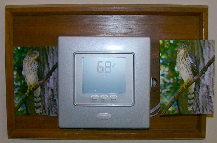 In December 2013 I had my 1967 oil burner furnace replaced after maintaining it for decades. I had had to fashion replacement parts for it as its manufacturer Iron Fireman no longer existed, nor alternative parts.
I might have been the last person on Earth who understood how it mostly worked. It pained me to get rid of it, but I had had enough of constantly working on it to keep it going.
The A/C was still working perfectly (although I had replaced the compressor's contactor numerous times and had also replaced its fan motor once).
Uncharacteristically, with the new oil burner I opted to get a new A/C system along with it because it offered a hybrid heat plant -- if the outside temperature is warm enough, it uses the compressor as a heat pump and automatically switches to the furnace when it gets too cold for the heat pump to warm effectively.
The new system works just fine, but the burner is no match for its predecessor Iron Fireman. The old one heated the house at 8 °F/hour and the new one at half that rate.
I guess in 1967 heating oil cost so little that they didn't care how big a burner to select!
My imperfect measurements show that it costs at last winter's prices about 24 cents to raise the house temperature each °F using the heat pump, while it is 64 cents for the oil burner. I used maybe 60% of the fuel I previously used (with larger electricity bills, of course).
I opted for the simpler Carrier thermostat, not the programmable one. I prefer to set it manually and not be bound to a weekly predetermined schedule.
One nice thing about this thermostat is that it has three programmable buttons (labeled Home, Away, and Sleep) that can be preset to any desired temperatures. So it only takes a single button depression for control most of the time.
In the past I actually just turned the heat off when I was out because the ancient furnace could heat the house up so quickly (and you get warm air from the vents in the process). I had to abandon that habit with the new burner because it takes twice as long to re-heat the home. As a result, I now had a more commanding reason for a remote controlled thermostat so I could start heating the house before returning. So in late October 2015 I worked on this project.
The big name in this field of course is Nest, and I took a quick look at it. Their webpage is woefully lacking in actual operational details. There is no operating manual! I'm aware that its claim to fame is the fact that it learns your habits and adjusts the settings automatically. But I don't want automation willy-nilly changing my settings without me understanding its internal algorithm. I assume that I can turn the learning mode off, but not certain about that. I also want to be able to walk up to it in person and easily change the settings. Not sure if the Nest lets you do that (no useful information on the website). Additionally, it costs $200 and is run through a cloud server. I would prefer not to put all of my home/away information on someone else's server and be dependent upon their security/privacy policies.
Next I looked at the Sensi™ Wi-Fi Programmable Thermostat. It looked pretty good. It's about $125 and clearly lets you manually control it locally. It also uses their cloud server which I don't like, but that's not a deal breaker for me. The big question for me is how it handles the hybrid heat. My current Carrier system has an outside thermometer; I can configure the switchover temperature for using the heat pump or oil burner, which I've set to 40 °F. After that it works on its own (you can override it to use the furnace instead of the heat pump). The Sensi (or nearly any other WiFi thermostat) does not accommodate an outside temperature sensor. I don't like that, but was willing to be reduced to actively selecting the heat pump or furnace manually (both locally and remotely). No actual operating manual on the website! What is wrong with manufacturers today? So I installed their phone app figuring it might be there, or at least I could see the real settings. But the app won't do anything until you create an account and presumably attach to a working unit. So I reluctantly called their tech support. After a while I talked to a fellow who seemed like he knew the real score. He confirmed that there was no handling of an outside sensor, but after multiple questions he told me that there was no user input that could select between the two heating methods. Instead, it handled it on its own. And its operating algorithm apparently is whenever heating is called upon: it (1) tries the heat pump for a while, maybe 20 minutes or so; (2) checks to see if the room is up to the set temperature; and if not, (3) switches to the oil burner. There are two things wrong with this mode of operation: (1) I want to be able to let it use the heat pump for hours, slowly raising the temperature by remote command -- which is why I want remote control in the first place. And (2) in the dead cold of winter when I don't even want it to attempt to use the heat pump, it will waste time trying it first. As an engineer, I find this so, so, stupid. Just let the user select automatic, heat pump, or furnace! Both locally and remotely. So sadly I had to eliminate consideration of this unit for my house.
To be fair, Carrier does sell their own WiFi thermostat, which I assume does everything I want. Prices seem to be in the $300-$600 range, so I didn't seriously investigate it. For all of these commercial systems there is also the installation question. My current Carrier thermostat is actually a two-piece device: in the basement on the furnace with a remote two-wire smart interface to the upstairs corridor unit. I would have to connect most thermostats to the wiring that is downstairs -- probably do-able, as I had a five conductor cable running from the first system anyhow. But I reverted to my do-it-yourself mentality...
I admit that it would be nice to have a fully functional WiFi thermostat, but in fact I doubt that I would ever really need more than a few simple functions. Plus the Carrier system I have now is smart and works just fine. All I really need to do is to remotely be able to push the existing Home, Away, and Sleep presets. Plus it would be nice to be able to remotely read the inside temperature. So I decided to build my own. I ran across a nifty device: the Electric Imp. It is a microcontroller module that incorporates WiFi and is programmed in a high level language, similar to various Arduinos. And it costs $20!
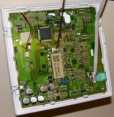 I carefully disassembled my Carrier thermostat and buzzed out the contacts for the three presets. This was not that easy to do because I couldn't really get to the buttons themselves, and separating the boards, etc. was somewhat risky -- I surely didn't want to damage the unit which probably would cost more to replace than all of these other alternatives. I successfully found the three pairs of contacts, which happened to have one lead in common, and brought out a four-wire cable paralleling them and terminated it in a Molex connector. After that it was certain to be easy to interface.
I built the Electric Imp onto a perfboard that contained three opto isolators (OFM-1A's that I have lying around) that output to the preset buttons, plus a thermistor that connects to an analog input. The Imp has its own built-in voltage regulator. I tried feeding it from the 2-wire smart Carrier interface which sits at 17v, but it interfered with the communication. So I recovered two more wires from the original wiring and put a 12vdc power wart downstairs at the furnace to power it (0.9 watt). I mounted the perfboard to the wallplate with Velcro, and I fashioned a U-frame with sheet metal that covers the board and attaches to the wood with Velcro also. Took me a few days to properly comprehend the programming and system operation that Electric Imp offers. They provide a server that the Imp runs Agent code on; and the Imp runs its own Device code. A realtime O/S is provided. Simply put, you enter a command through a browser which contacts the Agent on their cloud server; the Agent code sends a message to the Device; the Device sends a reply back to the Agent; and the Agent sends a response back to the original browser request. Now I know that this is using a cloud server which I would prefer not to do, but it is a general purpose microcontroller interface whose function is unknown; so the security aspects don't worry me. Still, I don't like being dependent on an external service. Maybe I will investigate bypassing their system and talking directly to the WiFi hardware, but that surely will be much more difficult.
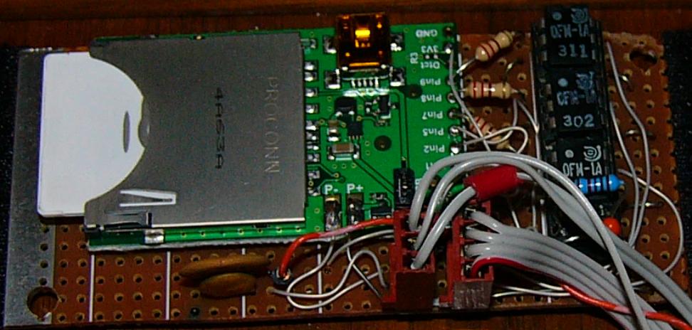 My code takes a command for Home, Away, and Sleep and pulses the corresponding opto isolator for a quarter second to mimic a finger depression.
It stores the most recent date/time of activation. Any command automatically sends back the Imp's status, which can also be directly requested. The status report shows the last command and the current house temperature.
It works quite well and I can even activate it without getting out of bed and walking to the hallway.
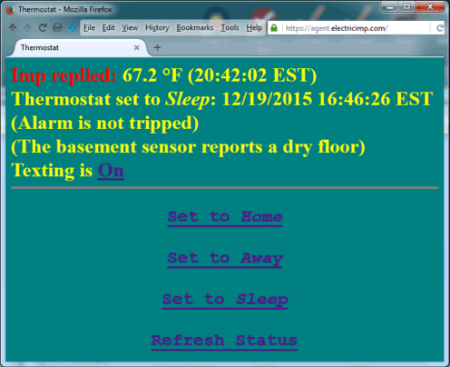

After the actual thermostat interface was completed the Imp had two I/O pins left over. But I only had one more unused wire through the wall to it. I was going to analog encode two signals until thankfully I realized that I could common the Carrier circuitry ground and the Imp ground, giving me two connections. So in December 2015 I added an OFM-1A optocoupler to my existing burglar alarm output and another one to the basement water detector (that just like the interface to its sister -- very easy, just power the device through the LED input). My Basement Doorway Pump works okay, but I have to remember to keep it clean from detritus or it can get stopped up. So it is useful to have a remote way to know that the floor isn't wet. The hardest part of this update was running twisted pair from the water sensor over to the furnace, where it could meet up with the wiring to the thermostat. So the Alarm and Water Sensor outputs filled the last two I/O pins on the Imp.
I did put bypass capacitors on those two inputs, but I was still somewhat concerned that spurious fields might induce some interference on those two long wire (antenna!) runs. I have the Imp sample each signal 100 times at a one millisecond rate; if ALL of the samples show active (low), it counts as an active signal; otherwise I discard it. Essentially a low pass filter. (I haven't tested to see if ham radio RFI interferes with it yet.) With that, it was easy to change the agent and device code to show the current status of those two alarms (seen above in the screenshot). But I would like to push an alert rather than relying on myself to continuously check its status.
The Imp's RTOS makes writing this kind of code quite easy: it doesn't even need a polling loop. An input pin level change can trigger a handler function (ISR, anyone?). When an alarm input transition is detected, I see if it is now active and previously inactive; if so, it's ready to send out an alert message. Before I even had looked into it, one of my students told me about Twilio. Among the many capabilities it offers is texting. I created a free account with them. It turns out that Electric Imp has an API specifically for Twilio. So now if the burglar or water alarms go off, the Imp texts my cellphone with an appropriate message. I don't bother texting if it disappears, as by that point I can check the webpage. Besides, neither alarm is going to extinguish itself anyway. I also added a Text On/Off function to the thermostat webpage, mainly for testing purposes. The only downside of the free Twilio account is that I have to use it every month to keep its number alive. I already have a list of things to do once each month (like run the backup generator for a couple of minutes, wind the pendulum clock, etc.); so triggering an alarm is now added to that list. It is a good idea to regularly test equipment anyway; otherwise there is no good reason to believe it will work when necessary.
I am very pleased with the whole system. Here is the (simple enough) schematic.
Security Cameras
 I don't have any particular reason to anticipate a need for security cameras, but I thought this would be an interesting project with the technology that has become commonplace.
With text alerts coming from the above project presumably informing me that the burglar alarm has triggered, it would be nice to be able to check and see if (hopefully) it is a false alarm or not.
I haven't had any spurious alarms in recent memory, but there have been occasional ones over the years. Never knew what to attribute them to, perhaps a line surge or lightning strike nearby.
The alarm itself runs off of a floating battery, so I don't really think any surges come directly from the mains; more likely induced voltages at the sensors. Whatever the reason, it will alleviate anxiety if I can see what's going on should I receive an alarm message.
The impetus for this project in December 2015 was that Walmart.com began selling prepaid Android (KitKat) smartphones for $9.82. I assume that Tracfone is subsidizing them, expecting to make money off of the purchase of minutes. But with WiFi, and just to use the device as a WiFi camera, I don't need no stinkin' minutes! And of course that $9.82 includes an AC USB charger. The short story is I bought five of the phones.
Here is the long story (you can skip this rant paragraph). Walmart's website (they don't sell these phones in the store, only via the web) says nothing about quantity restrictions. However, the radio button selector for quantity offers only one option: 1. Okay, I'm no neophyte online buyer. So I order one, then place a second identical order. Again, no indication that they only allow one per customer. The second order goes through immediately, approved, and I receive an email saying all is well and good. One minute later I receive a second email for that order telling me that there is a problem with the banking information for the credit card used, and my order has been "canceled by Walmart." Now, if they had simply told me that I already had one and can't buy another, so be it. But why accept the order, charge my card, then subsequently put the money back and tell me there is a credit card problem? I actually believed them and thought that my bank had refused the second order because it was for the identical charge within minutes and they perhaps thought it was a duplicate entry. So I tried a different card number from the same bank. Same acceptance followed a minute later with cancellation. Then I thought that maybe even though I used a different charge card, it was from the same bank tied to the same address and maybe the bank was that intelligent. So I tried a different card from a different bank (all with my identical address). Same pair of emails. I gave up until I picked up the one phone I had successfully ordered. Placed a new order, and it went through fine. I interpreted that to mean that Walmart didn't want more than one phone to be in process. When I tried to order another phone, same cancellation. So I figured I'd have to order each one individually and pick them up before buying the next. But this time around, it didn't work. So I tried a different shipping address (which is irrelevant because I was specifying the free in-store pickup). I did not expect that to work, because credit card transactions are verified by one of two methods: billing address comparison, or security code verification. I thought that Walmart would use the first method which would reject the incorrect address. But it went through! Only one email, not two. So I ended up creating multiple Walmart.com accounts with various useless addresses, even using the same credit card number. I am sure you are thinking that I am crazy for going through all of this, but I take it as a challenge and consider it a game, for entertainment purposes. Think what you will.
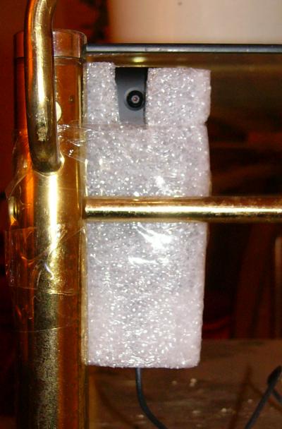 For each phone I configured them with most everything turned off, and logged into my WiFi router assigning each a unique dedicated internal network IP address.
I installed the free IP Webcam app. Configured it to boot to the app, put in username and password protection, and set each for a unique incoming Port.
With that, all I needed to access the cameras from my internal network was the individual internal IP and Port numbers. The webcam app offers a browser menu with various methods to see the live video. In order to access from outside the network, I configured the router to Port Forward each of the unique Ports to the corresponding camera internal network IP address. As long as I knew the house external IP address, I could sign in with that plus the particular port number to get to the desired camera.
To make it easier, I built a private webpage (in PHP) that generates a link to each of the cameras. If the http request comes from within the network (I am home) it creates links using the internal network addresses. For external http requests, the trick is to know what the house IP address is. Theoretically, since I am not paying for dedicated IP, the IP assignment is dynamic and can vary. In practice, the actual IP assigned to me has not changed in over two years. Prior to that it had sometimes changed monthly or more. But I have already built the understructure to handle this! My Birdcam uses a video feed from the house computer and has the same issues. In the house PC's Start Menu is a link to a private webpage that simply records the originating IP address. It stores it on my server, and the birdcam webpage generates the appropriate link address. So my Camera page generates the same external link using that information with no extra work. This method works because I generally boot my PC every morning which updates its IP address on the server. If that address changes during the day, it won't work again until I reboot or if I notice it all I have to do is re-access that special webpage. (If I wanted to I could just write a program to activate the identification page periodically, say hourly.) Now I'm sure you know that there are various cloud services which offer this same functionality. They must work in the same manner, having the remote device "call home" periodically so the cloud server can record the incoming IP. I don't know how often they send identifying packets. I prefer to do-it-myself instead of using a cloud server if I can figure out how.
I had an Android tablet in which the charge circuitry had failed. I had cracked it open and looked for bad connections but was unsuccessful in repairing it. Since it practically could no longer be used for any other purpose, I re-opened it and soldered a wire pair across the battery terminals through a protection diode, and brought them out to a connector. I thought a constant-voltage charge circuit could work. First I added another diode drop and powered it from a 5.0 vdc power wart. After a day it discharged, so two diode drops was too much. I removed the external diode and tried it with just the internal diode drop. Works fine, so I configured the tablet the same as the phones and used it as a sixth camera. Still, I am slightly worried that the Lithium battery might explode from overcharging, so that camera is in the garage.
Therefore I have six cameras that I can monitor at will. Not to get too creepy, the cameras basically monitor external door entrances. I mounted one on a tree a couple hundred feet from the house so I can see the road; I had installed a power outlet there when I had to repair a Romex break in the line that fed the house sign. I am thinking that I will be able to see if my road has been snowplowed or not with it. It remains to be seen if my packaging can weather the weather or vandals. That would be aggravating, but then again... it cost $9.82!
To any would-be burglars out there: I did this project just because I could. Really, honestly, truly I have no valuables whatsoever in the house! Primarily because I am a cheap S.O.B. Any targeted system can be defeated, and this one is no exception. But then again, I haven't told you about the automated offensive countermeasures I've also taken...
January 2022 update. The cameras have been working fine. One of the Walmart LG phones died so I bought a similar one off of eBay to replace it. However, two or three of them do lock up occasionally. This isn't so terrible for all of them except the one on the tree (need to get out the ladder, etc., in cold/rainy/snowy weather). Also, I need to know it's not working before I leave the house in case I want to check them while away. First I thought I'd look into remotely re-starting (Android calls it restart instead of reboot). Didn't seem quite so easy, and apparently in order to even accomplish a restart the device needs to be "rooted." Then I realized that instead of remotely restarting, it would be better just to have them restart automatically (say once a day) to pre-empt any problems. (IP Webcam starts up upon restart.)
I found just the app: Reboot Scheduler. As expected, it advises that it won't work unless the device is rooted. I hadn't done this before but was certainly aware of it. It is a little bit dangerous in that "rooting" really just gives the user/owner full privileges over the Android operating system -- so presumably one could "brick" the phone by mistake. I'm more worried about unintentionally installing malware which could wreak havoc in root mode. These types of apps need installation with an apk file instead of downloading through Google Play. To do so one must override the protections in Settings. I have done this before when installing older app versions that aren't available in Google Play, but it always concerns me. I have to be sure that the site I download the apk from is legitimate; this is hard to verify in many cases. Double dangerous for rooted devices! I did my best and chose Kingo Root. You can use a PC/USB to root the device or alternatively install their apk directly on the phone -- which I did. Wary, I first tried it on a semi-broken old tablet -- but it wouldn't install. Next I tried it on a retired Galaxy S4 phone -- and it worked.
So I trudged out to the tree to retrieve the outside camera phone (which is what prompted this whole episode). Rooted it and installed Reboot Scheduler now that I was somewhat familiar with the process. Had to test, of course. While I was at it I performed the same operation on two of the house cameras that sometimes are problematic (all of these phones seem to have different Android versions to add in a bit of excitement). Now they will restart once per day overnight. So even if IP Webcam freezes, or the phones somehow lose WiFi, hopefully they will restart as long as they have power and Reboot Scheduler is running (which it automatically does). I will have to see how it works out. This reminds me of many years ago when another student (RIP Kwok Li) was building a microcontroller for a Navy ship and he asked me about implementing fail-safe operation. I asked him if his hardware needed to retain data and he said no. I suggested he simply add a 555 oscillator to hardware reset the uP every so often. Very crude but effective!
Refrigerator Maintenance
 I bought this Norge 3-door refrigerator in 1983, and have been repairing it ever since. I liked the fact that it had a little separate freezer door just for ice cubes. This predated the now common icemaker/water dispenser mounted outside of the unit itself. My biggest problem with all of these appliances is that I only have to deal with each every few years -- so I don't remember the details or even the basics from the last incident. I try to take notes for myself but sometimes I don't even remember that a similar problem had previously occurred and don't look for any history.
I'm sure that there were more incidents than listed here, especially prior to when I moved from a paper checkbook to Excel.
- August 1998: Appliance Repair of Baltimore replaced defroster heaters $240. This might have been the first repair that I just behaved like a normal consumer and called a repairman to handle. But I saw how he disassembled the insides to get to the defrost coils and that was fairly simple to replicate in the future. I believe that I bought replacement coils at least once or twice and did the swap myself.
- December 2002: D&D Appliance Repair replaced defroster heaters $159. Except apparently I had forgotten that I had replaced these coils myself and called a repairman again!
- June 2007: replaced condenser fan motor (Aireco) $23.83. This is the motor in the back that blows air across the cooling coils. Impossible to purchase a direct replacement, but I managed to adapt mounting to accommodate the new motor.
- July 2007: filed Temperature Controller's contacts. This is the unit that turns the compressor on when the temperature rises above the setpoint (28 °F) and turns it off when it drops down to another setpoint (13 °F). When I saw how much the replacement cost, I decided to see how long I could make it last just by filing and cleaning the contacts. See December 2014 for the answer!
- Some month 20xx: I have no record, but I know that I replaced the defrost timer at some point. Pretty easy.
- June 2013: replaced original compressor relay with solid state relay (Aireco) $5.98. The compressor motor has "Start" and "Run" terminals. The original design I think was quite smart: when too much current flowed through the Run circuit, it would activate a relay that powered the Start circuit. As the motor turned up to speed, the Run current automatically dropped which in turn released the relay's power to the Start circuit. The replacement is probably more reliable because it is not really a relay (even though the package identifies it as a "solid state relay"); all it really is is a PTC (positive temperature coefficient) fuse, which is in series with the Start circuit which is always connected. So the Start circuit is connected when the PTC is cold (low resistance) to get the motor running; then, apparently, once running the Start circuit draws an excessive amount of current which heats up the PTC thereby reducing the steady state current to a low level. With the original component, should the power flicker off while the compressor was running, it would power up perfectly properly because of the sense current trip. Now, if power is lost while the compressor is running -- meaning that the PTC is hot and high resistance -- when power resumes it won't supply the Start circuit with enough juice to get the motor turning. (If power is lost for several minutes, the PTC cools down and therefore the start-up cycle is normal.) What I haven't mentioned is that in addition to the startup relay or PTC is an overcurrent sensor on the Run circuit; when that trips, it interrupts current for a timeout period. But the timeout period is shorter than what the PTC requires to cool down, and in fact even though there is not sufficient current flowing through the PTC and the Start circuit to get the motor running, Ohm's Law keeps the PTC warm so it won't cool down enough to be ready for the next cooling cycle. While it is possible that if I let it spin its wheels on its own for a long enough period it would eventually restore operation, all I really have to do is unplug the refrigerator for 5-10 minutes which is plenty of time to let the PTC cool down and then plug it back in. But in the back of my mind is the question: what happens if there is a brief power flicker when I'm not home or don't notice it? I have never found the unit warming up on its own, so perhaps it works after all -- just not as elegantly as the original configuration. Note: it is amazing how well the human brain can do pattern recognition. When the Run overcurrent relay kicks out and in, and then the (original) Start relay activates for a few seconds, the sound sequence is quite definitive. If the motor is unable to reach operating speed quickly enough, it creates a clicking sound cycle of off/start/on which I noticed. That is how I even knew that something was wrong with the start circuit. The problem would not occur at once, but get gradually worse. I eventually learned that a repeated cycling indicates a problem, even for those times where it successfully got itself running normally.
- August 2014: defrost heaters (Air1Supply) $18.95. This is one of the times I remembered that I knew how to replace the defroster coils. Harder to obtain the exact replacement, but found similar enough ones.
- December 2014: Temperature Controller (Appliance Zone) $59.87. The contacts were too deteriorated for repair, so I bit the bullet and bought a replacement.
- February 2016: Water Inlet Valve for icemaker (Appliance Zone) $19.25. My icemaker was working, but I had fewer and smaller cubes than proper. These units use dead reckoning for the water volume, i.e. they activate a water solenoid which turns on the water inlet for a predetermined number of seconds. In this case, the existing solenoid was just acting sluggishly and was not opening fully to permit the proper flow which would fill the tray correctly.
- March 2017: Icemaker tray (RepairClinic) $16.45. My original icemaker was a mechanical marvel. It filled the tray; after freezing, it rotated the tray until it was upside-down, but at first catching one corner on a halting stud; since the tray is plastic, the turning motor distorts the tray as it bends causing most of the cubes to fall into the collection bin; then the stud retracts and the ice tray slams flat (upside down), which hurls any remaining cubes into the bin; then the tray rotates back to the original upright position and the cycle repeats. On this occasion, I was finding that more and more of the cubes would not fall out of the tray; so on subsequent fill cycles it eventually overloaded the tray and water overran into the bin. I spent too much time trying to clean and buff the tray to smooth it out to its original condition; alas, even though it really seemed slippery and smooth, it still didn't work. Amazingly I found the exact replacement icetray and it worked perfectly. Until...
- August 2017: replaced Icemaker (Appliance Zone) $63.25. I don't see any record, but I know that I had repaired the icemaker mechanism at least once. This is harder to do than you might think, because there is a cold sensitive mechanical component that expands and contracts to prevent the icemaking cycle to operate unless it is indeed freezing. So once I pull the unit out of the refrigerator/freezer, of course it does not operate sufficiently for me to even figure out how it's supposed to work. But I had figured enough of it out to make repairs. Until this time! Disassembling the unit, I found the culprit: the main gear driven by the timer had three teeth ground away. Probably it had been operating blithely while first one, then two, teeth disappeared; but three (consecutive) broken teeth was just too much. Now I know that it is very difficult to repair gear teeth, but I gave it a shot: I drilled and tapped holes to take three #2-56 bolts which I screwed in and filed down.
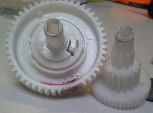
 In fact this actually worked to drive the gears. But I subsequently found that the spot where the screw heads were was used by some type of cam sensor. I knew this was probably a death knell, but I filed the piece down which was getting stuck on the screw heads; then it turned properly, but of course whatever the cam was for would become inoperative. Now I fully admit that even after extensive examination, I really do not understand how this amazing mechanical contraption works. I did take a couple of photos before total disassembly, but to even get to the point where that is possible it is necessary to remove enough stuff which causes parts to pop out with various springs. So while I think that I made some very good educated guesses as to how to put everything back together, my confidence level on that is low. Also, remember that it will not even operate unless it is cold enough? So all I could do is try to put it together and re-install it and see if it works. Which it didn't. Which means I needed to come up with a new plan.
The first plan is to just use old-fashioned ice cube trays and forget an automatic icemaker. I was willing to accept that if necessary, but on to plan #2:
It goes without saying that I was unable to locate an identical replacement icemaker. Which means could I find another icemaker that I could cajole into working in my 1983 Norge? At first this didn't seem that tough. But suppliers list pieces by the manufacturers' part numbers and assume that you are replacing one part with an identical one. And they show part numbers by refrigerator model number. But I could use neither of those identifying numbers, so I just scrolled through the pictures. They expect you will transfer small pieces from the old (broken) unit to the new one. Some units require another subassembly which isn't identified or noted. Eventually I did find an icemaker that was fully self-contained (except for the water inlet solenoid which is mounted in the back where the water comes in and I had just replaced anyway in February). Of course I knew that I would have to do some re-wiring and somehow get the water fill tube routed to the proper place.
 The wiring is pretty simple, with four contacts: case ground, 120vac hot/neutral, and solenoid power. The new unit which of course used a different connector kindly came with an adapter jumper for another refrigerator model (which also does not match the Norge) -- so it was a simple matter after buzzing out the new connections (actually I had to manually rotate the timer to get the solenoid output to trip in order to determine which of the power leads were hot and neutral); I cut off half of the adapter and replaced it with the old Molex connector.
Now I had to mount the icemaker; the new model uses two mounting screws on the left side, but my old one mounted in the back of the compartment. I thought about just drilling some self-tapping holes in the refrigerator interior, but instead just used some old PCB board stock to fashion a bracket to place a second mounting hole; I used one of the original spots for the new unit. I intentionally mounted it a bit lower than I think is intended because I don't like it when icemakers tend to overload the container bin and the ice cubes fall over the side.
 Lastly I needed to re-route the water fill. At first I just put a plastic tube over the existing tube (which originally fed a trough to the old icemaker but is at the left and doesn't match the new one) and let it just drop the water into the middle of the freeze chamber. At the time I didn't quite know the exact positioning and timing. Eventually I learned that on this device it fills when the ice is about 90% lifted out of the trough, and the tube poured water over the newly extracted cubes. Which worked but is obviously not a good idea. So over to the hardware store and get a right angle plastic elbow (31¢ and six inches of 1/2 inch plastic tubing (45¢, I had black opaque tubing but thought it would be neat to use transparent tubing instead to be able to see the water inrush). The tubing fits inside the elbow and a small section over the original fill tube mates with the top half of the elbow.
Everything works great. Plus I learned how modern icemakers work. More intelligent than bending a plastic tray, it heats the bottom of the freeze chamber just prior to scooping the cubes out. Should this one break it will be a simple matter to get an identical replacement.
I am pretty sure I know what you're thinking (beyond that I'm obviously crazy): "You fool, don't you know that if you discarded this anachronism and bought a modern refrigerator that it would save you money because those are much more power efficient?" My calculations show that the break-even point is ten years. Now, I ask you, how much confidence do you have that a new refrigerator will even work without repair for ten years? I know I'm being recalcitrant, but my attitude is that the best way to recycle equipment is simply to keep it operating. So I intend to repair this one as many times as it takes until either the compressor goes bad or there is a Freon leak (yes, it is old enough to probably contain actual ionosphere-destroying Freon).
Home Monitor
This project is a major expansion of my four-year-old WiFi Thermostat which used an Electric Imp microcontroller to remotely control my house thermostat. If you look back at that project, you can see that it also texted me should the home burglar alarm or basement water sensor activated.
Some background. The house was built in 1967 by K3TGU. Not only a ham, at the time he was a technician in the Baltimore County Radio Shop; Bill was technology-aware and used that knowledge when designing/building the home. I greatly appreciated these efforts! Mainly there was wiring between the first-floor rooms through the attic to the rafters in the unfinished basement (inevitably the wiring wasn't always where I needed it, though!). A very neat wiring method for the various house lights was utilizing low voltage latching relays to control the 120VAC powering them (you will shortly see why I'm mentioning this.) There are two nifty General Electric control panels (Master Bedroom and Kitchen) that control those relays; a few of the lights have additional low voltage switches also attached. I appreciated this as an engineer because it means that it isn't necessary to route actual AC power wiring to the various switches, only low-power control leads. The relays work by momentarily activating an ON or OFF lead (at the control panels by rotating the ON or OFF selector button to the desired light and depressing it). Remember, this was constructed in 1967, long before arrangements such as X10 existed. Here are pics of the opened wiring box and its controller:
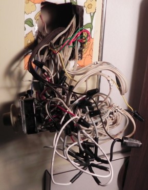
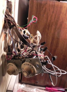
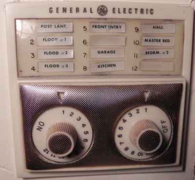
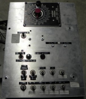
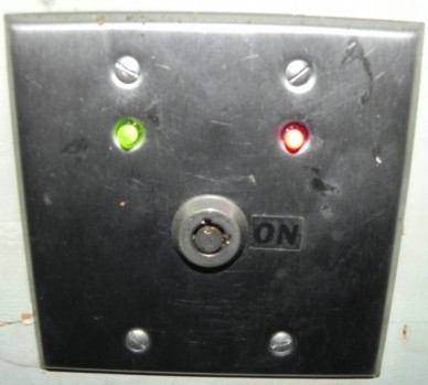
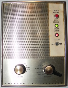
Alarm System. One of his more complicated systems was the burglar alarm, shown directly above. It mostly consisted of two sections: a keyswitch module mounted in a panel in the garage, and a second box situated in the basement. There is another panel in the Master Bedroom along with a house siren; the garage and bedroom panels each house a Sonalert(TM) as well, plus a red and a green LED. The wiring from the bedroom panel leads to the garage panel which in turn feeds the basement box. All of the door switches terminate separately at the basement locus. I doubt I'm giving away any secrets by describing how it worked: the alarm could be turned on either by a switch in the bedroom panel or the keyswitch mounted on the garage panel. While activated, if any of the door switches (or a radar-based motion sensor upstairs) shows a door open or motion, the green LEDs extinguish (green indicating all is secure) and the Sonalerts(TM) generate a tone. An exit time period (set by the garage module) permitted one to close doors and leave without tripping the alarm. Once the exit time was reached, the red LEDs turn on; then any interruption of a door sensor or the motion detector latches the incursion and an entry timer begins. Should the alarm be turned off wherever it was turned on from before the entry timer elapses, all is good. Should the entry timer expire before the alarm is turned off, the alarm trips. Once tripped the only way to turn it off is with a reset button in the basement control box. Upon trip, the house siren is activated for several minutes and a number of house lights and floodlights are turned on (through the low-voltage wiring).
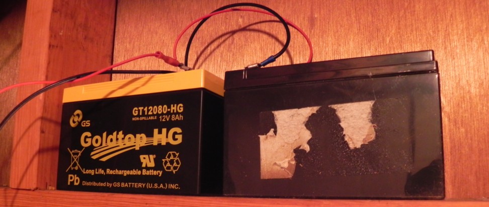
The basement box provides interconnections between the elements, connects to a 12VDC power supply and backup batteries (above). It also included toggle switches to enable/disable any of the door switches and motion sensor. Bill had kindly left me documentation for the system plus over the years I had traced out some of the control box wiring. I mostly understood how it worked. There were a number of times that I had to repair various pieces and my documentation might not have been up to Bill's standards; I know I had made repairs to the radar sensor and some transistors in the garage control unit (lightning surges?) on more than one occasion. I vaguely recall years ago that sometimes (rarely) I would come home to find the lights on and the alarm tripped without knowing for sure what precipitated the trip. Malfunctioning aged door switches and funky motion detection were the primary causes, though. But in recent years for some reason I hadn't had any false alarms. It was a pretty good, if ancient, alarm system!
52 Years is Long Enough. As an engineer and tinkerer, I have a special appreciation for anything built that has a long and useful lifetime. (I always thought years ago when I saw a mechanical cash register in a store that obviously had been in use for decades how proud I would be if I had been its designer!) This alarm system had been in daily use since 1967! I had added the texting output for trips, but still it had lived out its useful lifetime. The basement box was relay logic with a mechanical darkroom type of timer (well, for sure I have lost digital-only photographers who have no knowledge of the development timer widely used while chemically processing actual film in the dark). Still, I am certainly known for extending the life of old gear. However, the last straw came a few months ago when I left town for a week and on the very first day (before actually arriving at destination) it texted me a (false) alarm. I was surprised because I hadn't had one of those in a long time and the bad timing was worthy of Murphy's Law. I quickly checked the video cameras and saw nothing wrong and asked my neighbor to double-check. But I really wished that I could know what had tripped the alarm, and furthermore be able to reset the alarm. So essentially I was alarm-less until I returned and reset it. I (probably correctly) guessed that the culprit was the motion sensor; so I disabled it and had no other false trips. But the seed had been planted in my mind and there was no escape.
New Alarm Architecture. It was obvious that I simply needed to move the alarm task from ancient hardware to software running on the already web-connected Electric Imp. I just needed a bunch of I/O ports around the house for it. I was familiar with Maxim Integrated's 1-Wire family (originally Dallas Semiconductor that Maxim purchased). In fact, I had used their button as part of a project (Line Securer for Capital Telecommunications). It's called "1-Wire" but of course you need a ground wire, too -- making it really
The 1-wire communications protocol is not really an async serial port but closely allied to that. With just a diode and a pullup resistor a standard TTL UART (serial port) can directly drive the 1-wire bus. These parts have been around quite a while, and the Electric Imp library included drivers for it, using the internal UART. I bought a few parts, wired up a test Imp, and was relatively quickly successfully connected using library functions. But that was not my plan -- it was the backup plan. Having the Imp's UART directly drive about a hundred foot long star-configured bus didn't seem a super-smart idea. More recently, Maxim came out with the DS2480B Serial to 1-Wire Line Driver chip. This intercedes between the microcontroller's UART and the 1-wire bus itself. It has the capability to shape the communications pulses, providing variable source and sink currents to best match the 1-wire line. This part should make the communications channel more robust.
Alas, there was no DS2480B function in the Electric Imp library. And that affects communications protocols to all of the downstream 1-wire peripherals. So I set out to write my own interface code for it. Didn't seem that tough, there were several app notes describing it. I even found C-code for other processors for it. The problem was... it just didn't work!
In retrospect (as is typical) the problems shouldn't have taken that long to overcome. I think I spent about three weeks resolving this! First, the specifications require a long logic 0 before getting the 2480B's attention. Sounds simple but not so easy on the Imp. Once the UART function is activated, those pins aren't directly controllable as I/O bits (which is reasonable). I was concerned about switchover glitches. Of course prior to configuring the UART I can write 0 to the Data Out pin and then configure the UART. But the timing and the glitches were a problem. All I really needed was the ability to transmit a Break signal through the UART interface, but the Imp library does not support that action. The other way to effectively create that break signal is to first configure the UART for a slower bit rate and send 0x00 (which Maxim suggests). Which is what I was doing. However, the very next action must be to re-configure the UART at the proper bit rate. That re-configuration possibly glitches the output. Which is critical because the 2480B detects the rising edge to commence timing measurements that it uses for the rest of the communications packet. I was concerned with the possibility of this creating a problem, but I was side-tracked due to receiving reasonable responses back from the 2480B!
To initiate communications, after the break signal, one sends 0xC1; it is supposed to respond with 0xCD. I consistently received a different response. Out of desperation I wired up a second 2480B to make sure the first one wasn't defective. Of course the same response. Okay, it seems that I should work on this comm initialization matter. But I was fooled into skipping exploring it more because the subsequent commands I sent it returned the correct responses: all of them. Clearly I was successfully talking to this part! Now there are two types of protocols: those that configure the 2480B, and those meant to be relayed through the 1-wire line to the other 1-wire peripherals. All of the configuration commands (except that darn 0xC1) responded properly, but none of the downstream commands seemed to actually be communicating with the peripherals. One other detail: the 2480B responded to a second 0xC1 command that I tried out of desperation -- never the first as it is supposed to. Down the rabbithole I went.
Better that the configuration commands not work! Then I would have had no choice other than investigating the initialization itself. I tried so many things, like various timing delays, etc. to no avail. I stared at scope traces (and needed better triggering options, too) seemingly seeing peripheral (incorrect) responses. After a lot of effort, I thought I needed to step back and verify commands and responses independently from the Imp itself. I wired up a MAX232 RS-232 to TTL interface chip from a UMT-1 to connect the 2480B to a serial port on my PC. Then I tried HyperTerminal and next PuTTy terminal programs, but neither provided a means to transmit or receive binary (hexadecimal) codes. I even fired up an old Dos-based Procomm. No dice. Okay, I am up to this. I had to remember how I coded my ARONTS software, written in Turbo Pascal, to build my own hexadecimal in-and-out terminal program. But I still needed to send a Break out the serial port and had no software ready to do so. I had to write directly to the PC's 16550 UART, and I finally found the port definitions (once upon a time these were easy to find). So I ended up with a nifty hex terminal program that could generate breaks.
The good news was that it communicated properly with the 2480B: I received the correct 0xCD initial response, although again only after I repeated it a second time. I need to add that one of the 2480B app notes provided a configuration packet recommended for initialization; I blithely was sending this precisely without necessarily investigating what each command accomplished. When I manually sent these commands through my fancy PC hex terminal program, I received the proper responses (as I did earlier with the Imp). I still wasn't connecting properly with the downstream peripherals. Since I was manually typing in these commands, it was easy to put them in one at a time, so I first started by not sending them -- and I talked to the peripheral! So I added in one configuration byte at a time; the very last byte killed the comms. I looked it up, and duh, it transmitted a zero out the bus (never releasing the bus afterwards). Of course that kills communications. I remain bewildered why Maxim includes this in the app note with no further discussion.
This test told me that there was something different between my test arrangement and the Imp implementation. I looked more closely at the scope traces and indeed did see a glitch when re-configuring its UART between 4800 and 9600 bps. I was trying to figure out a way to eliminate it, like using up another output I/O pin to OR with the serial out during the transition. Then the obvious hit me: it wasn't really outputting a zero, it was temporarily placing the TxD pin in high-impedance or input mode in between the UART configuration commands. Which isn't that crazy to expect. So the solution was simply to put a pullup resistor on the pin! You're probably thinking I'm a real numbskull for not thinking of this two or three weeks earlier. The resistor, deleting the last configuration byte from the packet, and still repeating the initial 0xC1 command had the Imp communicating downstream with the 1-wire peripherals. I have never found an explanation as to why I need to send the first initialization command twice; there would be no disadvantage to doing so other than imperceptibly slowing down the comms by adding an unnecessary byte.
With the 2480B, commands are buffered between the UART and the peripherals; commands and responses are pretty simple using the 2480B's comm protocols. Which is different (and simpler) than directly driving the peripherals from the UART itself. I could not use -- and had no need for -- the peripheral Imp 1-wire library functions; I wrote my own to replace them. At this point, I could communicate properly with the peripherals. With one detail remaining...
All 1-wire parts have an individual unique embedded 64-bit identification number used to address each part over the common bus. There is an algorithm to discover all 1-wire chips on the bus in order to enumerate them and obtain each part's ID. I had used that library function while directly communicating through the UART (bypassing the 2480B) which had worked from the very beginning (which caused a very positive emotion). I couldn't directly use that function through the 2480B, however. It writes and reads individual bits rather than bytes that the 2480B provides. I should have been able to write my own discovery function through the 2480B using Maxim's documentation, but truthfully I really really did not want to have to do that. Also, I don't really even need that function in the end system; I just needed to be able to discover the ID's for each of the chips I had purchased, which would then be hard-coded in the operational code. And I could simply bypass the 2480B and discover those addresses in the beginning. But that seemed kludgy and I wanted to be able to enumerate through the 2480B. After wringing my hands for a while, I guessed that if I replaced the subroutines in the library function to write and read bits via the UART with the actual 2480B commands to write and read bits on the 1-wire bus, that might work. Luckily, it did! A sigh of relief.
The 1-wire peripherals I selected for this project are the DS2408 8-bit I/O port; the DS2413 2-bit I/O port; and the DS18B20 temperature sensor. Next I wrote general purpose I/O routines to communicate with each and tested them on a breadboard. I should note that neither of the I/O port chips are available in DIP version. I was forced to solder flying #30 wires connecting the surface mount leads to a DIP header which I could plug into a socket. Lots of use of magnifying glasses! I was able to test the flying wire hardware carrier connections and I/O functions at this point. All that remained was to construct a few boards and write the operational code. (Only one time in my technical life have I ever failed to write such code from an equivalent test stage.)
Other Functions. The main uses of the Home Monitor are the existing thermostat control and the new version of the alarm function. Once I had a 1-wire interface it was trivial to populate DS18B20 temperature sensors all around (they cost $3.17 apiece). Upon trip, the old alarm activated four of the DC controlled lights/floodlights (via a relay). It didn't turn them off, that was a manual action. I liked this feature and wanted to provide for it in the new alarm as well. Bill had run a quad cable between the kitchen lighting control panel and the downstairs nexus. The four ON wires were brought down separately and controlled by a 4PST relay. As an alternative I opened up the kitchen panel box, removed those four wires and instead put in five 1N4007 diodes (I added in a fifth light) so that I need only send a single wire downstairs for the ON function; then did identical diode wiring to also bring down a single OFF control. (I had decided that I wanted to provide for an OFF function, too. When a tripped alarm is deactivated, the uP now automatically turns off those five lights.) This wiring is shown (very sloppily) at the top right of page 5 of the schematics below. The pictures of the wiring are far above, next to the GE control box; the two sets of five diodes (one set each for ON and OFF) are in the star configuration heatshrink wrap at the bottom of the left photo.
As an aside, I am often away and watch my home Xfinity X1 DVR through a Slingbox. Yes, Comcast provides an app which provides a similar function (but I bought the Slingbox before they even offered the app), but it isn't really playing your home box -- but an equivalent network source. And it blocks NFL games which defeats the entire purpose of remote access. They also provide a means to remotely issue a reset DVR box command. It goes without saying (but even so, I'm saying it!) that if the DVR crashes and loses connectivity it cannot receive the reset command. This happened to me once and so I had added a separate AC powerline controller so that I could remotely power it down and up to reset it. Never happened again, but better to be ready than sorry. Anyway, I wanted to add this functionality into the Home Monitor and remove that separate powerline controller.
My bed has a heater with a long time constant. If I'm away for more than a few days I would like to be able to turn it off upon departure and turn it back on a couple of days before return to give it time to come up to temperature. I had added a second separate AC powerline controller for this purpose and I also wanted the Home Monitor to replace that too. (One of the new temperature sensors monitors as well.)
Hardware Arrangement. Schematic Drawings and Wiring here.
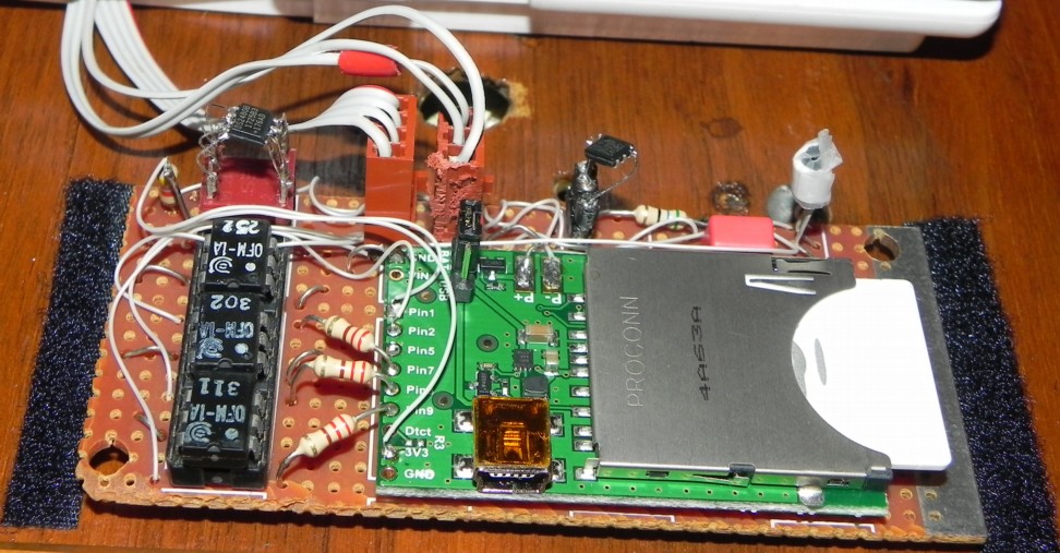
At the Thermostat. The Electric Imp microcontroller remains mounted at the thermostat in the upstairs hallway (shown above). The board and arrangement from 2015 is the same as far as controlling the thermostat itself, shown on page 2. The updates are on page 1: the three wires connecting to the basement are now the 1-Wire bus (ground, +5v, 1-wire); I eliminated the +12v wall wart in the basement previously powering it because it is now powered by a +5v regulator in the furnace unit, and isolated its ground from the thermostat circuitry (which I had only placed in common previously because I had run out of connecting wires). The circuitry containing the DS2480B connects to the UART pins 1 and 2. The thermistor temperature sensor and 1% 10K resistor are removed and replaced with a DS18B20 temperature sensor.
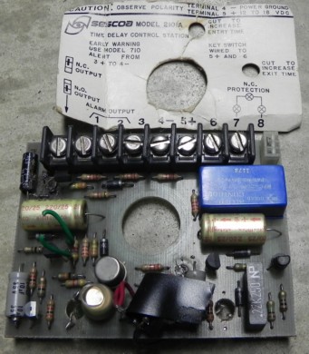
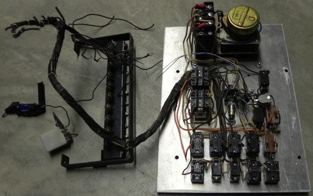
Main I/O Unit. Most of the hardware is mounted in the basement, where the bulk of the connecting wiring terminates. The original hardware (above) was removed. The new board (on page 3) contains two DS2408
In order for the N-channel FETs to control Lights On and Off, I had to reverse the polarity (sorry, Professor Brown) of the lighting relay control to provide a common negative return. It was fed by a half-wave rectified 30VAC transformer, and that rectifier was Selenium! I am (just) old enough to have seen and maybe even used selenium rectifiers. Back in the 1960's semiconductor diodes were germanium with very low voltage and current ratings. I have known about that selenium rectifier in my basement for 36 years and it made me smile to think about it. But now I finally replaced it with a 1N4007 silicon diode when I needed to reverse the polarity.
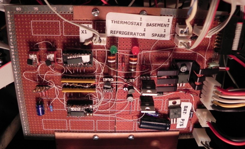
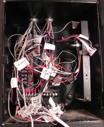
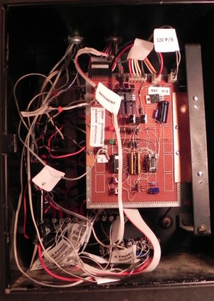
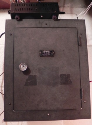
Upon installation it was with great trepidation that I ripped out the old hardware; there would be no going back! I did mark what I thought was everything. Turned out I had not actually found the siren wires; instead I had only located the parallel garage bell. One of the numerous unmarked brown wires was the powerfeed to the siren itself (in the attic). It took about ten minutes or so to identify them by trial and error. After this board was wired in (along with the microcontroller board upstairs) I powered up the system and it worked. On to the rest!
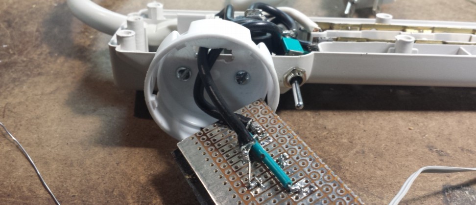
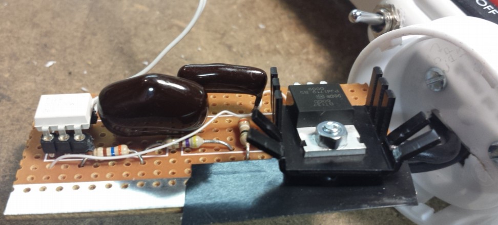
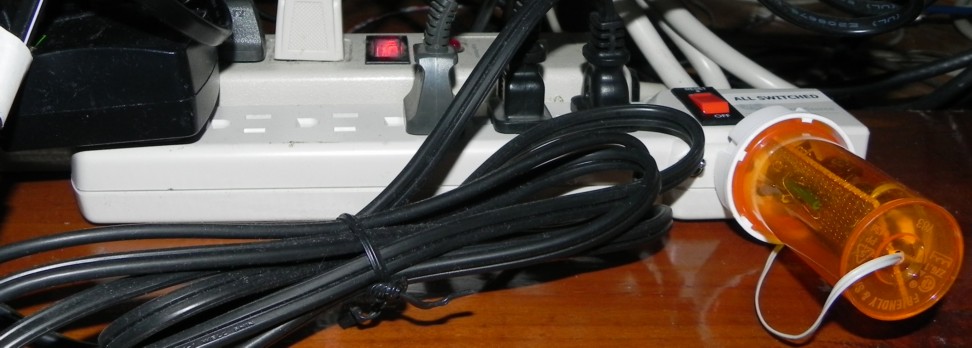
X1 Unit. It's not that far (through the floor) from the X1 DVR to the basement unit, so I included in the Main Unit a current source to activate a powerline control for the DVR. I (sort of) put the triac circuitry inside a powerstrip and ran a separate pair between it and the main unit. Included is a toggle switch that bypasses the soft control. I didn't bother to build in automatic powering if the system is powered down or offline from the uP because that would necessitate an alternative power source, so if I'm shutting it down for whatever reason I just have to remember to bypass the X1 control with the powerstrip toggle switch first. The schematic is on page 6. The DVR only draws 29 watts (27 off, so don't even bother turning it "off") so I used a solid state triac switch -- there is minimal power loss or heat there. I plug the Slingbox into it too, so I can reboot it along with the X1 (but I can't recall it ever having a problem). You can see above that I put the circuitry inside an attached pill container (wasn't that much space inside the strip).
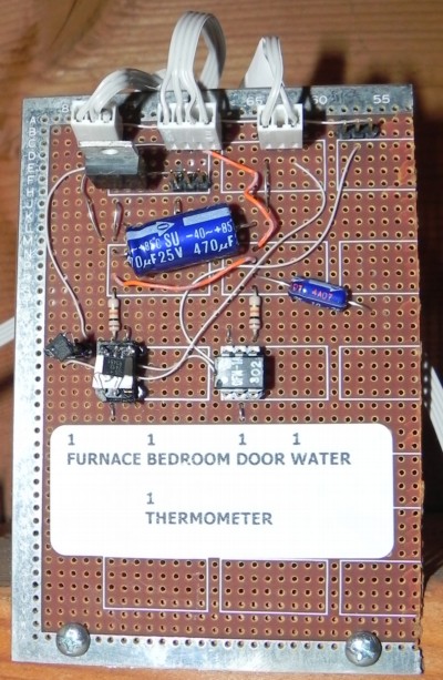 Basement Unit. This board (schematic page 7) is mounted above the outside basement door. There is a doorswitch that runs from the door to the Main Unit box. I had previously connected a Basement Watchdog water sensor to the Imp by running a separate wire pair to it. The Basement board replaces the doorswitch detection and the water sensor output with a single DS2413 2-bit I/O port, necessitating a single 1-wire run to the Main Unit instead of the two separate runs. The original doorswitch run used a shielded two-wire cable, and I had thought that I could just use it for the 1-wire run. But attaching it killed the 1-wire bus. I guess way too much capacitance. So I used the previous water sensor twisted pair plus just the shield wire from the doorswitch run for the 1-wire bus, and that works fine.
The Basement Watchdog nominally uses a 9 volt battery which in its previous iteration I had replaced with a 12vdc wall wart along with a small optocoupler interface. I wanted to eliminate this separate power supply, and the Main Unit already has 12v; so instead of sending +5vdc along the 1-wire bus, for this one spot I fed it with +12vdc instead. But I still needed +5v for the temperature sensors, so I put another 5v regulator on this board for them. The board attaches to two DS18B20's -- one mounted inside for the basement temperature, and one through the outside wall for the outdoors temperature readings.
Bedroom Unit. I wanted to provide for the bed AC power control and a temperature sensor for it. My original plan was to build an identical triac circuit for it as in the X1 powerstrip. My natural inclination is to eliminate all moving parts (I went to great pains to build a completely solid state telephone switching system with no relays). But this heater draws 286 watts and I will turn it off only very rarely. My measurements showed that the triac dropped about a volt with this load and would continuously dissipate over a couple watts. So a normally closed relay contact (which automatically handles the no connection/power down state) really makes much more sense in this instance. As shown on page 8, this board controls that relay; I had an extra I/O pin available so I put a pushbutton on it. Activating it toggles the bed heater power through the Imp.
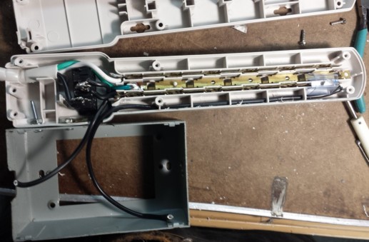
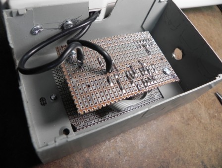
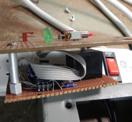
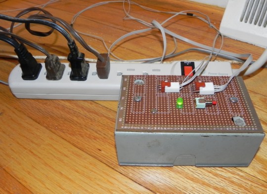
I mounted this on a box attached to another powerstrip like the X1 arrangement. I rewired the powerstrip internals so that only one of its outlets was switched. That actually was fairly difficult to do because of the physical setup. When you look at the board photos don't worry -- the top board has only low voltage isolated circuitry on it. Only the lower board with the relay connects to the power mains. This bedroom is directly above the basement door, so a short run through the floor connects this module to the basement board. I could have used a 5v relay, but it consumes 79ma while the 12v version draws 33ma; so I added a fourth wire between the two boards to minimize power drain, plus it bypasses all voltage regulators.
Refrigerator. You might note that I have a bit of a refrigerator quirk (to put it nicely); I decided to put temperature sensors in the freezer and refrigerator compartments. I knew the biggest task would be to get the 1-wire bus inside the refrigerator itself without drilling holes and possibly compromising the insulation. The wire is only a 3-conductor flat ribbon cable, so it takes up very little space or width. I managed to remove the rubber housing that feeds the icemaker water inlet pipe and place the ribbon cable through it prior to reinsertion. It's a little hard to see it in the picture below left; the ribbon wire is hiding underneath the red wire. You can see the freezer sensor (and my lying thermometer, which displays 10 degrees colder than the DS18B20 reports!) and the refrigerator compartment sensors below. Once inside the freezer compartment, there is a variable louver that sets the freezer temperature, which provides a path between the two sections to run the 1-wire. I had to do the soldering etc. on the kitchen floor after running the wire. I swear this whole process took two or three hours.
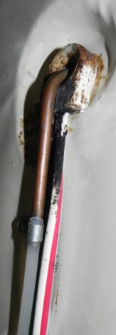
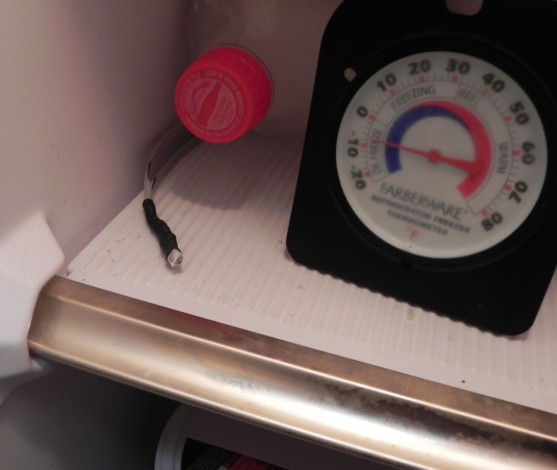

I was somewhat concerned from the beginning about the length of the 1-wire run. My initial tests on the breadboard of course worked fine; when I placed a hank of wire between the elements on the breadboard it still worked, but with some (tolerable) comm errors. I wasn't sure what I was going to find with the actual final implementation. Which is partly why I first tried it all with just the thermostat and main unit boards; then added the basement unit, with its wiring complication; then the additional run upstairs from there to the bedroom. The final run to the refrigerator was the longest, maybe 35 feet. When I connected the two refrigerator sensors, the Discovery function properly enumerated all of the devices, which sounds good. The refrigerator 18B20 returned a reasonable temperature, but the freezer 18B20 returned a crazy out-of-range output. While I had meticulously wired both of those TO-92 sensors and sealed them with heatshrink while sitting on the kitchen floor, in my mind I was convinced that I must have wired the freezer sensor incorrectly. Which indicates a mind malfunction, because it enumerated properly. The +5v line isn't necessary for identification, though, and somehow I was thinking that it was wired wrong. But I really really did not relish the thought of tearing it apart just to check.
I had been using an 18B20 software conversion function from the beginning that had always worked flawlessly. I don't even remember where or how I had come up with the conversion algorithm (maybe I can blame it on extraction from the Imp library?). Upon closer inspection, I realized that the fault was there. The 18B20 reports a signed binary value indicating the Celsius result. Inside the freezer, this was the first instance I had with a negative value! The code simply was wrong; I fixed it and breathed a sigh of relief that I didn't need to fool with the sensor wiring on the floor again.
Door Switches. For an unknown reason, there were two outside doors which did not already have closure switch sensors. Maybe the radar motion sensor was intended to handle these cases? But for completeness I added magnetic sensors to each. This is certainly the simplest hardware operation of the entire project. Only the task of getting the wiring downstairs invisibly presented a challenge. I think it took me three and two hours each!
Control Software. I had dipped my toes in the water programming the Electric Imp for this project's first implementation in 2015. I was fairly confident that I knew enough to carry through to this version, simultaneously knowing that there were a number of areas that I would have to explore anew. Hard to say exactly because I kept adding in stuff sporadically after it was operational, but I'd guess there is two weeks of coding here. As I mentioned in the first version, this platform makes use of Agent code running on a cloud server, and Device code running (duh!) on the Imp device.
Device Code. While testing on the breadboard (with the DS2480B) I had built my own 1-wire library and tested it. The platform incorporates an internal log which lets one send outputs from both the Device and Agent sources, so this is what all the testing makes use of. The earlier software version had nothing for the device to do on a regular basis; it responds to communication from the agent by registering response functions automatically; it also handled input pin changes (for the alarm and water detection pins) the same way. So there was no actual Main code after initialization in that version -- everything ran from interrupt or operating system requests. Now I went to a more traditional methodology, running a control loop indefinitely while still responding asynchronously to agent requests. I also had to implement some setups which would let the device actually continue to keep running my code should it lose WiFi connectivity (the default has it spend all of its time trying to reconnect).
Communications. I logged a number of 1-wire communications errors. It took a while to come up with a reasonable way of reporting them. First, if the device machine-guns error outputs at too high of a rate to the platform's logging function, it stops logging and partially disconnects temporarily. It was aggravating to regain control quickly. Second, I don't want the log output to be inundated with not-useful error messages, hiding more relevant ones. I built a two-tier approach: the first comm error that occurs generates a logged error message; subsequently it will only report another after an hour elapses. It continues to keep a cumulative error count even while silent, so while it will report errors at most at one-hour intervals, it tells how many total errors have occurred since restart. This is mostly an oversight report; individual errors don't really have any significance because the code bypasses them. This brings us back to the discussion of utilizing the DS2480B in the first place. My initial programming did not make use of the pulse shaping ("flex mode") it provides for simplicity. Especially after adding the refrigerator's 1-wire run, I had quite a few comm errors. I re-perused the app notes and turned on flex mode with some suggested pulse shaping parameters. This helped a lot, although at this time I still encounter in the range of a dozen errors per day. Each command packet initializes the DS2480B with 6 bytes; each DS2408 output/input packet adds 14 bytes; each DS2413 output/input packet also adds 14 bytes; so each I/O port uses a total of 20 bytes. There are two DS2408's and four DS2413's totaling 120 bytes per update cycle. That update cycle runs at about four times per second for 480 bytes per second of throughput (there is also a millisecond delay incorporated in each DS2480B initialization) so the 1-wire bus is handling about 41.472 MB per day. I'm excluding the DS18B20 transactions because they only run once per minute. The error rate is therefore 0.00003%. I'm not sure if that is reasonable or not; I might tinker some more with the DS2480B's pulse shaping parameters.
That logged error reporting is helpful for system analysis, but isn't what is needed on an operational basis. I want to be alerted if there is some type of hardware failure (wiring or board/chip level). So the second half of my comm error reporting deals with burst errors. Separately from the above reporting process, should 10 comm errors be encountered within a 10-second window, it alerts me (with text and/or email) because something needs to be fixed and the usability of the alarm system is questionable. It also will only repeat such alerts at most at (separate) one-hour intervals. I can always remotely turn off texts and emails if I wish from the web interface.
Nonvolatile Parameter Storage. The Imp is pretty much always powered due to the backup batteries. But still it makes sense to store operating parameters into nonvolatile memory. The O/S offers single store and retrieve functions -- I'm assuming to/from the flash program memory. All I have to do is pack and unpack the list into a single blob element to make use of them. On device reset it reads those parameters and updates program variables. Each time the web interface (Agent driven) changes a parameter (such as using each door, or texting or emailing), it sends the data to the device which saves the parameters in its flash. I don't place them in persistent server (Agent) storage because I want them to take effect should the Imp restart without an internet connection.
Update_IO. The program maintains at a high level variables that ultimately are output to the various I/O pins (for instance Red_LED, Siren_Out, etc.). The function Update_IO outputs to all DS2408's and DS2413's, setting the output pins according to the appropriate signal variables. At the same time it gathers data from all DS2408 and DS2413 input pins. Such inputs do not automatically update high level input variables (such as Basement_door); should it sample two identical inputs in succession, it updates the appropriate variables. This method automatically handles switch debouncing, and ignores any type of not-detected onetime comm errors. When comm errors are detected, it simply ignores that sample. Should some type of not-detected comm error cause an incorrect output, it should be automatically corrected upon the next cycle. Update_IO runs at about four times per second. This lets the rest of the device code simply deal with the high level output and input variables.
Timers. The Imp O/S provides a millisecond timer. There are a number of variables that store when various activities commence; these are loaded with the current time when started. Each activity (like alarm exit delay inside Handle_Alarm) just tests the current time - the start time to determine if time has expired for a particular action. Several timers are kept for the outputs that are pulsed: Lights On/Off and the three thermostat buttons: the activating code simply sets those variables True and initializes a timer; Update_IO automatically outputs them on its next call. It also checks all of those timers: whenever they expire Update_IO sets the matching output variables to False which causes it to clear those outputs. In the first version of the Thermostat-only program I more simply wrote a 1, delayed a fraction of a second, and wrote a 0; but this method fits more with the polling-all-actions main loop.
Handle_Alarm. Alarm progress is covered here. It is essentially a state machine which checks inputs and timers for each possible alarm state, updating outputs, timers, and the next alarm state as appropriate. The bedroom Panic Button is also processed here, which immediately sets off the alarm. It incorporates internal logging and messages the Agent when alerts are appropriate. At all times the green LEDs illuminate when all enabled doors are closed and similar; if not, they are out and while arming or armed the Sonalerts(TM) activate. During the last 15 seconds of the exit delay, the red LEDs blink; so if they aren't blinking, I know that I have at least 15 seconds to re-enter and exit without a trip. Once armed, the red LEDs stay on (off while disarmed). During the last 15 seconds of the entry delay, the Sonalerts(TM) beep at about 2 Hz. So if they're not beeping, I know I have at least that amount of time to turn the alarm off before a trip happens. Once the alarm is actually tripped, the Sonalerts(TM) are latched on and it pulses the Lights On relays to turn the floodlights etc. on; activates the Siren if it is enabled; and texts and/or emails me as set, with the message stating the source of the alarm trip. The Siren turns off after a while. When the alarm is reset by any of the three available means, it turns the Siren off, pulses the Lights Off relays, and either disarms or re-arms the alarm according to the switches and web activation configuration.
Process_Bedroom_Reset. This function is used by Handle_Alarm. The original alarm system, when triggered, could only be reset at the main basement box. While this new system permits resetting via the web interface, I also wanted a means to reset it from the Master Bedroom switches. I only had the two inputs there and also didn't want to make it too obvious, so I came up with a particular sequence that also resets tripped alarms. This function implements a separate state machine with timers to detect such resets.
Handle_Bed_PB. This trivial function is in the main control loop. It just monitors the pushbutton on the Bedroom board to permit simple local toggling of the bed heater instead of requiring web control. The green LED on the board illuminates when power is applied. I could have inserted this function inside Update_IO or Handle_Alarm, but doing either would seem to violate the definition of those routines.
Handle_Water. The original implementation used a pin-change interrupt to detect water sensor changes, but that method is no longer usable. This simple function sends alerts (text and/or email) through the Agent if new water is detected and at least an hour has elapsed since the last similar alert. The only way it can repeat is if water arrives (generates an alert), it dries up somehow, and an hour or more later water re-appears. I have seen this happen with just a tiny amount of wetness, but usually I will have to dry it out myself before another alert could be sent. I don't want to be reminded over and over again that I have some mopping to do, plus once alerted I can always look at the real-time status on the web page.
Handle_Temperatures. Once per minute, a Measure your Temperature command is broadcast to all DS18B20 temperature sensors. One second later, each sensor is individually polled for its updated temperature, and the matching program variable is updated. If there is a comm error it just leaves that reading alone. It checks temperature ranges for all of the readings except the outdoor sensor; if any of these range windows are violated, it messages the Agent to send out a temperature alert. (So far my cellphone has alerted me one time telling me to shut the damn refrigerator door because I'm warming the food! I guess I should call this Dad mode. I have configured my cellphone to startle me with a 20-second long alarm clock sound when incoming texts arrive from Twilio.)
The DS18B20 is rated at +/- 0.5 °C (0.9 °F), so I have fairly high confidence in the returned values. However, for the sensor mounted at the thermostat, I found with the previous iteration's thermistor measurement that it fairly consistently read about 4 degrees high. I had put a -4 °F correction figure in the software. With the DS1820B in the same location I find that I need a -5 °F correction. I'm trying to match what the actual thermostat displays (but it only shows whole degrees), because that helps me while away to decide when to change the temperature setting. My guess is that there is some amount of heat generated by the Imp and its corresponding circuitry, but it doesn't draw much power. It should be cooler now because I'm feeding it with +5v instead of +12v; there is an internal voltage regulator, but then again it is a switching regulator so it shouldn't dissipate much anyway.
Last week I noticed that the outside sensor was up to 90 °F when it wasn't really that hot; I guessed correctly that the Sun was hitting it. I added a cardboard sunshine shield and that worked.
Once per hour all temperatures are assembled into a single CSV line which is sent to the Agent. (The Agent sends it to a separate PHP program on my website that appends a temperature spreadsheet file.)
Agent Handlers. For every Agent command (generated by clicking on a link in the displayed web page) there is separate handler code. They mostly update a configuration variable, store it to nonvolatile flash, and return all current conditions back to the Agent to re-display the status page. Disabling or enabling a door, or setting email notifications on or off are examples.
Main Running Code. The above Handle functions do everything other than handling requests from the agent (those Agent Handlers are called asynchronously). I know I'm weird, but I smile when I look at the entire operational code:
    function Run_Forever() {
        imp.onidle(Run_Forever);
        Update_IO();
        Handle_Alarm();
        Handle_Bed_PB();
        Handle_Water();
        Handle_Temperatures();
        }

    Update_IO();  //so that the next call updates all inputs as the second sample
    Run_Forever();
The onidle line tells the Imp's O/S to run this function whenever it has nothing else to do. I found out that if you simply create an endless loop it does run, but the Imp will no longer respond to the Agent or the IDE (Integrated Development Environment). Regarding the timing, Run_Forever is taking 234 ms. per cycle. I can easily tell this because the red LEDs blink and the Sonalerts(TM) pulse at a ~2 Hz. rate. My calculations can come up with 137 ms. I'm losing 97 ms. somewhere. (I could greatly speed this up by programming the DS2480B to place the 1-wire bus into a high-speed mode; but I don't think this would be advisable because I'd expect more errors and perhaps RFI.) Maybe the O/S is using those 97 ms. to check for internet messaging. I could test this by putting multiple loops inside one Run_Forever cycle, but then the timing would become staccato so that the input change recognition and the blinking/pulsing would be less consistent. That also would slow down the O/S response to incoming messages from the Agent, which would slow the response to a web browser click. Because Update_IO requires two consecutive identical samples to change input settings, all actions are essentially delayed a half second. Which is perfectly fine. But I can notice it when I close the kitchen door and go to turn the alarm on. I can see the green LED turning on. The original hardware alarm system was of course observably instantaneous.
The program initialization runs the Discover code and enumerates the 1-wire device ID's like this:
12 Onewire chips discovered:
0: 0xAA 0x00 0x00 0x00 0x32 0x3C 0xED 0x29 (DS2408)
1: 0x2F 0x00 0x00 0x00 0x32 0x3C 0xEA 0x29 (DS2408)
2: 0x5E 0x00 0x00 0x00 0x4E 0x00 0x97 0x3A (DS2413)
3: 0xDC 0x00 0x00 0x00 0x4D 0xE4 0x9D 0x3A (DS2413)
4: 0x24 0x00 0x00 0x00 0x4D 0xE4 0x96 0x3A (DS2413)
5: 0x35 0x00 0x00 0x00 0x4D 0xFC 0xCA 0x3A (DS2413)
6: 0x94 0x00 0x00 0x0B 0x1E 0xA4 0x0D 0x28 (DS18B20)
7: 0x5E 0x00 0x00 0x0B 0xAC 0x24 0x81 0x28 (DS18B20)
8: 0x6C 0x00 0x00 0x0B 0x1F 0x3E 0x01 0x28 (DS18B20)
9: 0x4F 0x00 0x00 0x0B 0x1F 0x53 0x16 0x28 (DS18B20)
10: 0x17 0x00 0x00 0x0B 0x1E 0x00 0x7C 0x28 (DS18B20)
11: 0xC2 0x00 0x00 0x0B 0xAC 0x11 0x28 0x28 (DS18B20)
As I added the boards and chips into the system, I copied and pasted these addresses from the log into the program's list of physical device ID's. The logical identifications are then assigned to the physical parts.
Presently the code is 1506 lines long, which occupies 36% of the codespace. Interestingly, I cannot find any specification for how much program memory this now discontinued Imp001 module contains! The later (and currently available) versions all show 256MB. I could download the code to an Imp004m device I have and compare the percentages.
I intended to activate a fairly standard watchdog timer for failsafe overall protection in case the processor would stop executing my code. There is no such function in the Electric Imp that I can find. Searching the developer forum there was no useful dialog on that issue to be found. Most of the discussion related to connection to the agent, which presumes that the device is properly running the O/S. When the module loses connectivity it automatically attempts reconnection which I think includes a built-in reset, but my initialization to keep running during WiFi outages might remove that form of automatic reset. I have never encountered an actual crash, so I'll just keep my fingers crossed!
Agent Code. The agent outputs the HTML to a browser that displays the Device's status, and provides the links to change its settings. The status looks like this screenshot:
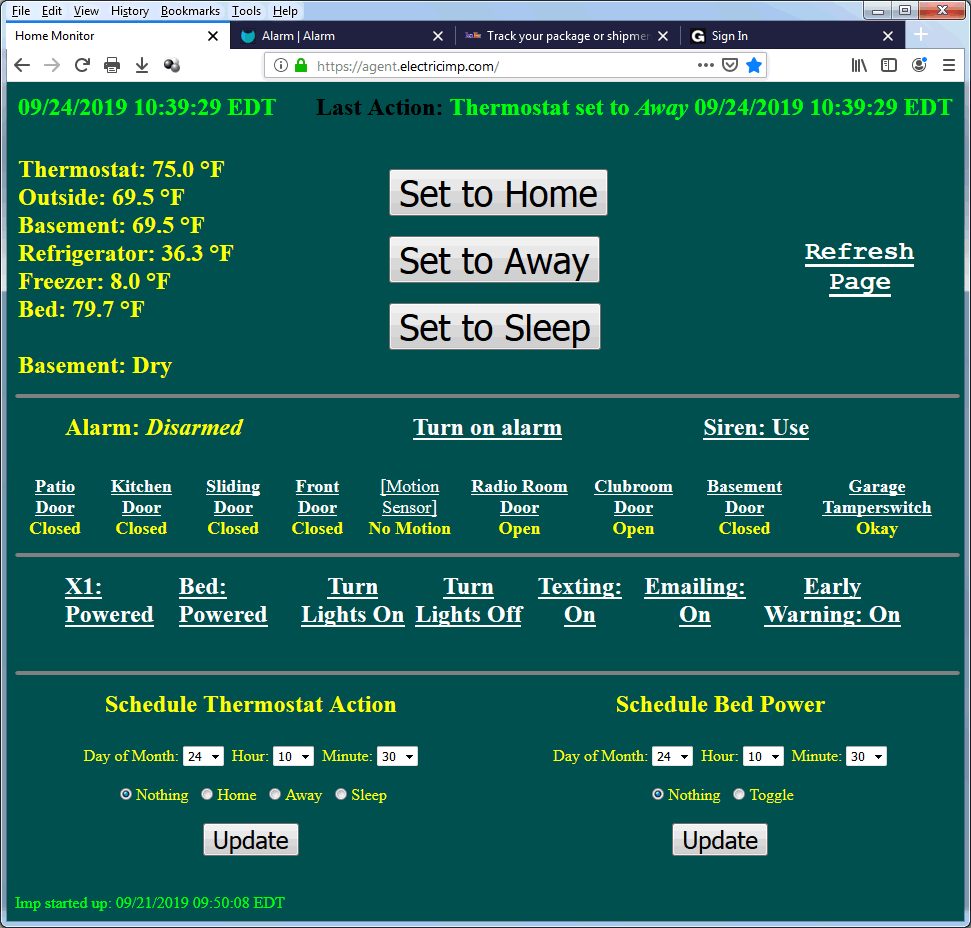
Text automatically reformats according to the browser width and font size (just automatic HTML); I squeezed it down a bit to make these images. The top left date/time displays when the status was requested. Last Action at the top right shows the most recent web action. It is intended as somewhat of a security check to inform if something has occurred that isn't from me. It doesn't show actions that were taken on the premises (those might be in the Imp's log file, though). The six temperatures display at the top left along with the current status of the Basement Watchdog monitoring the floor. At top central remain the three thermostat setting buttons, and an easy-to-click Refresh Page option is at the top right.
The current alarm status is shown below the first horizontal line separator. As depicted above it is disarmed. If I forgot to arm it when leaving the house, Turn on alarm lets me activate it remotely:
which illustrates that it also displays how far along it is in the arming state. I also had clicked Siren: On first to disable the house siren in case I inadvertently set the alarm off while making these screenshots. If I had turned the alarm on before leaving I wouldn't have had to web enable it, and it would show:
Bedroom Enabled displays when appropriate. After the exit delay, the left status simply shows Alarm: Armed. If I needed to deactivate the alarm remotely, I can just click Turn off alarm and get:
Once armed, if an enabled door opens, the alarm latches:
and then:
(the alarm can still be turned off without a trip) finally followed by:
which displays Tripped, Siren indicating that it is in that alarm state irrespective of the fact that currently the siren is disabled. Turning the siren back on would immediately activate it at this point.
The right side of this section permits enabling/disabling of the house siren as previously mentioned. The next line of the screen shows each door sensor: whether it is enabled or not plus its current status. If the description is in boldface without [] brackets surrounding it, that source is enabled and will trip the alarm if breached. Clicking the door's description toggles its enabled/disabled status; for instance, in the initial screenshot above the Motion Sensor is bracketed and not in boldface; it is currently disabled. Unrelated to the agent code, in the device code I have it log the fact that a disabled source would have tripped the alarm, mainly to try to track down suspected false alarm problems.
Moving to the next row for discussion are seven links. They all are toggle functions except for the Lights options, which turn on or off the five wired floodlights (they are automatically turned on upon an alarm trip and off when the trip is reset -- so these options are not needed simply for alarm handling -- I guess I included them for testing and just because I could, plus they're fun). Starting at the right is the Early Warning option. In the old system the only output from the alarm to the Imp was an actual trip; but now I have more possibilities. I asked myself "Why do I want a text alert telling me that someone has already broken into the house and actually tripped the alarm? Why not warn me that they are in the process itself?" So if Early Warning is on, as soon as a door is opened while the alarm is armed, a text and/or email alert is sent. The disadvantage of this is that sometimes after I have armed the alarm and left I want to quickly re-enter and grab something; I know I'll trigger the alarm but I can re-enter, do whatever, and turn it off and back on before leaving again. I know that the entry delay is in progress and I have the time to do all of that before it trips. So now in this case I'll get an alert on myself even though the alarm never actually goes off. Not sure if this is a great idea or not, hence the toggle option!
The Texting and Emailing toggle options permit me to select how I want to receive alert messages. Used mostly during testing. For example, with Early Warning on I will receive an alert such as this:
The actual source of the trip is shown, plus any sources which would also have initiated a trip if they had been enabled are shown in brackets. The above alert is due to the Early Warning feature, but whether that is enabled or not, should the trip turn into an actual tripped alarm state, an alert such as this is sent:
The door statuses sent are the values that latched the trip itself; the status might have changed since due to closing a door after breaking in.
At the left side of this section I can power up or down the X1 DVR and bed heater.
The last section of the web page lets me schedule one future action each for the thermostat and bed heater. This looks pretty simple but it took me an entire day to write this code! I've been meaning to add this for a while with the previous code implementation but just never had gotten around to it. I don't particularly want a programmable thermostat (as is common) because my schedule isn't all that regular. But on many occasions I set the temperature to Away when I leave and intend to change it to Home remotely an hour or two before I return. More often than I'd like to admit, I forget that second piece until I'm already driving back. This scheduling feature lets me set it as I expect to need it when I leave; I can always change it while away. The default is the current calendar date and time; dropdown boxes let me alter each and select the Home, Away, and Sleep option to be activated at that time. For instance:

I can remove a scheduled action just by changing the action to Nothing. Bed power scheduling works the same way, except that it toggles; in practice, I turn it off directly and program it to toggle back on. Once an action occurs, it shows up in Last Action and that particular schedule is disabled.
 [3/3/2020 update: I finally got around to adding a feature I had thought about for a bit: automatic thermostat programming depending on the outside temperature. My HVAC system is hybrid, meaning that for heating it either uses the oil burner or the heat pump. The heat pump is more efficient dollar-wise, but doesn't perform well if it is too cold outside. I have it set to use oil if it's colder than 40 degrees (it has its own outside temperature sensor mounted on the compressor unit), otherwise the heat pump. Consequently, the outside temperature informs my decision as to when to effectively turn the heat on or off by altering the Home/Away/Sleep buttons. While away, if the temperature is going to be below 40 all day long I just use the above time scheduling to turn it on with sufficient time for it to come up to temperature by the time I return. If I know it will likely go above 40 I want to wait to start the warm-up until then. I had been monitoring and changing the setting manually accordingly. This new feature lets me pick a temperature and tell the Imp to change the setting on its own when the temperture either rises above or falls below the selected outside temperature. This dropbox defaults to 42, but a range of degree settings are provided. Next either the < or > radio button is selected instead of the one adjacent to the Day selection. After also picking Home, Away, or Sleep and clicking Update, the temperature trigger is used instead of the datetime method.
Similarly, I usually hit Sleep manually before retiring; but if the temperature is currently above 40 and is expected to drop lower overnight, it is more efficient to let the heat pump run while it can but go to the lower Sleep setting once the outside gets too cold for it. Now I can just set it to switch to Sleep when the temperature drops below 40, trapping as much cheaper heat in the home as I can.]
The above commentary describes the user interacting with the webpage, but it takes actual code in the agent to accomplish these things!
requestHandler. The requestHandler function has the agent listening for web browser clicks; it looks at the various options the user has selected and chooses an appropriate response code function to handle it. The largest piece involves displaying the device status. This is the fun part: the user makes a click; the agent code sends the device a message, telling it what parameter to change; the device packages all of its internal variables and parameters into a single serialized structure and sends it to the agent; the agent unpacks this information and uses it to construct the HTML for a display page; which it then sends back to the originating browser, displaying the response to the initiating click.
Texting. Texts are handled identically to the previous software version, using a trial Twilio account. Thankfully, Electric Imp provides a Twilio API to call.
Email. This was a lot harder than it should be. I have successfully programmed in Python a method to access my own email subscription provider to send out emails. But as far as I can determine there is no means to do this with Electric Imp's Squirrel-based platform. Scouring the developer forum, I was able to implement outgoing email using Mailgun, which provides a usable API. Had to open a Mailgun account. The free version has an ugly "from" listing, but it works well enough.
Remote_Log. Every hour the device sends all of the current temperature readings to the agent. I want to permanently record these. Electric Imp provides a means to store "persistent" data in their cloud (which I use for the thermostat and bed heater schedules) but this has a limited size. I couldn't find a direct way for the agent to store an actual disk file, so I wrote a separate webpage on my own server in PHP. This accepts a line of csv data (actually it could be anything) and appends it to a fixed file on my server. I wrote agent code which takes the device-sent csv temperature line and invokes a web call to that server page. It is implemented in a function call that asynchronously returns a response. If the response is good I ignore it; if it is a bad response I also ignore it (so big deal, the temperature log misses one entry) but have the agent log the error. The failures rarely happen and I'm not sure why they would occur -- that's the internet for you. At any time I can easily download the accumulated temperature file which neatly can be presented in an Excel chart:

which shows hourly readings from 8/8/2019 through 9/24/2019. Certainly not necessary, but cool!
HandleProgrammedActions. All of the code described above is event driven. The agent is responding from an http request from a browser or a message sent from the device. It has no idling running code at all. I needed to implement the scheduled thermostat and bed heater actions based on date and time. I could find no O/S option to schedule anything based on the datetime, however. What can be done is to schedule a function call after a specified elapsed time. I thought about scheduling two such calls, one each for the thermostat and bed heater based upon the scheduled time less the current time. But I took the easy way out: the HandleProgrammedActions function wakes itself up every minute. On each activation it checks to see if this minute is the proper time to issue a message to the device to accomplish the scheduled action. If it is, it simply sends the same message to the device as if it were initiated from a browser click. Turned out that I still had to change the code a little, because the browser-based actions instigate a status response back to the agent for web page display. Here, there was no browser http call and nowhere to send the response to. The agent was smart enough to ignore that formality, but it was ugly; so I added a parameter to the device message to tell it if a status response should be sent or not.
When I added the temperature trigger thermostat action, I kept all of the programmed parameters in the agent code. While such a trigger is waiting, I have HandleProgrammedActions simply send a request to the Imp every ten minutes to return the outside temperature. That response activates a separate agent function that compares the current retrieved temperature against the comparison value; when the threshold is met, it does the same thing HandleProgrammedActions does when the specified datetime is reached.
Wrap Up. The agent code is currently 658 lines in length, there is no limit I'm aware of.
I knew that this would not be a simple project. It was a little more time-intensive than I had anticipated, though. I ran into a number of problems along the way which were not shocking and fixable -- but overall added days to resolution. I'd say that it took about three months from beginning to end. The alarm was cut over and was operational with the Main I/O Board only on August 27, 2019 and this Home Monitor fully put-in-service on September 11, 2019. Part of my goal was to learn more about writing code for the Electric Imp, which I certainly did. I know this description is verbose, but I'm proud of the design!
With all this discussion of a burglar alarm, I reiterate here what I wrote about my home monitor cameras: "To any would-be burglars out there: I did this project just because I could. Really, honestly, truly I have no valuables whatsoever in the house! Primarily because I am a cheap S.O.B. Any targeted system can be defeated, and this one is no exception. But then again, I haven't told you about the automated offensive countermeasures I've also taken..."
Furnace Repair
See my opening paragraph in WiFi Thermostat. The whole reason I replaced my ancient furnace was that I tired of constantly repairing it. The new hybrid system worked flawlessly since its 2013 installation. But on November 2, 2021 in the late afternoon (Tuesday) I noticed the house seemed cold. My furnace wasn't working! With both an oil-burner and heat pump, I did have redundance built-in. Unless the problem was a common element. I quickly determined that the blower motor wasn't turning. Of course, it is needed for both methods. The furnace was still under warranty so I thought I could avoid self-repair. How quaint.
Since I had to wait until the next morning to call the HVAC company I did a little more checking. Old-fashioned blower motors are pretty simple: apply 120VAC and they turn; remove power and they stop. Very easy test. The new, efficient, variable speed blower motor my modern system now had -- not so easy. There is a 120VAC power connector, but also a 16-pin plug that carries control signals to the motor. I did some googling and found the required signals needed there to get the motor to turn and indeed those voltages were there and the motor didn't do anything. I was 99% certain that the motor itself had failed.
Time-wasting sidetrack: Needless to say, the house was getting somewhat cold. The outside temperature was in the 50's, so it wasn't as bad as it would be in January or February, but still -- not comfortable. Figured I could jury-rig a temporary measure. When the old furnace was removed, I saw the old blower and associated squirrel cage assembly and kept it instead of having them haul it away. I put a plug on it and stored it in the garage. Figured it might come in handy if I needed ventilation for some future reason. It definitely worked at that time. So while neither the blower motor itself nor the squirrel cage would fit into the new furnace, I could abut it to the opening and maybe duct tape it to blow air into the furnace to get heat into the house. I'd have to manually turn it on and off. But the best laid plans... The motor wouldn't work right! No worry, I had accumulated a couple of other simple blower motors over the years (but I didn't recall if they worked or not). I swapped them into the squirrel cage and ended up swapping motor-start capacitors as well. I finally got one to turn and for a short while I achieved some heat distribution throughout the house. But the motor itself got quite hot and I didn't think that it would be a good idea to keep it running. So after wasting a few hours for sure, I abandoned my short gap measure. So close!
I called the installer the next morning (Wednesday). Silly me, I thought I could just bring them the faulty motor and pick up a replacement since it's still under factory warranty. I had chosen not to pay for an annual service contract (which it turns out would not have covered anything at all anyway) so I figured they'd charge me to actually come out and do the diagnosing and repair even if the parts are supposed to be free. First problem: they had no replacement blower motors. They could order from Carrier, but Carrier wouldn't ship for two weeks (if that, this is during the pandemic supply chain slowdown). Second problem: while the actual blower motor will be replaced for free under warranty, they will charge me $220 for "processing warranty paperwork and ordering it." What a crock! And this is for me delivering and picking up, not them doing the actual service. I might have been tempted to pay them if they had one in stock. I didn't have to use this company, the one that installed the furnace, but I did have to use a factory authorized company in order to get the "free" replacement motor. I was going to see if I could find any such local servicers who might have stock, but they wouldn't really have much incentive to help me. The motor itself lists for about $800. While searching, I got a little confused about the part designation because there was reference to more than one piece, including an electronics assembly which was or wasn't included. This got me to thinking...
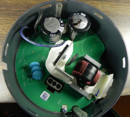
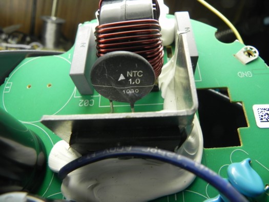
I looked more carefully at the motor. It appeared to be one piece, but in fact there was a removable section in line with the motor proper. I guessed that this housed the electronics module I had seen referenced, so I disassembled it. Mind you, I have no internal circuitry description for this so I'm flying blind. Nowadays with specialized IC's and surface mount parts there is often little hope that something can be diagnosed and repaired. But it's worth a look for something broken even though I didn't want to invalidate the "warranty." Once I got the assembly off of the motor I immediately bellowed "Hallelujah!" There was a leaky electrolytic capacitor (above left)! I removed it from the board and measured effectively zero capacitance. I was 100% certain that it was defective (this isn't unusual for these parts) -- but I didn't know if there was anything else on the board that had also gone bad. Nothing else looked faulty but I didn't do any real checking. I have many parts on-hand, but search as I did I could not locate a usable 200 volt/1000 mf cap in the house. So I ordered two from Mouser at $5.75 each and paid another $22.99 for overnight shipping. It's now Wednesday so I'll have the part on Thursday.
I come home from school Thursday afternoon and immediately retrieve my package. It didn't take much time to replace the cap, attach the assembly to the motor, and plug it into the furnace proper. Honestly I gave it an 80% chance of working. I turned on the circuit breaker and the furnace, and... nothing! Oh well, I gave it a shot.
I can't give up that easily. I pull everything back apart and look more closely at the board. True, this is a complicated motor-control unit. But the complicated part is in a lower potted portion that I had no chance of addressing. This board has only two wires leading from it to the potted section (the 120VAC power socket is on this part). I realize that this board is merely a DC power supply. So I carefully wire up power to it and measure the voltages on the two electrolytics. There's maybe a volt or two there and these are 200 volt caps. I remove power and begin to trace the AC wiring. It goes through what I assume is a line choke which measures good. It then passes through a disc part which I'm pretty sure is an inrush current limiter (above right). When I inspected things the day before I hadn't noticed anything wrong with it but on closer viewing there are some small cracks in it. More importantly it measures high impedance. It has a marking "1,0" on it which I think means quiescent one ohm. Which it certainly wasn't. Again I search the house and couldn't find anything suitable but cut out one I had put into Telesaver switches decades ago. It isn't the proper value (it is 10 ohms) but its purpose is to limit power-up current surge while charging the caps. It's not rated at the 10 amps that's shown on the motor housing but I don't think the motor actually draws that much current (rated 3/4 HP). I short it across the faulty one on-board, apply power and get out the voltmeter. Now I have 350 volts on those two leads going into the mystery section! I really am certain this will work.
I put everything back together and indeed my furnace is now working. I'm a little bit leery of the replacement inrush current limiter I used, but figure I'll wait until I have more stuff I need to order instead of ordering any now. I'm mad at myself for not fully checking the board before I placed the overnight order -- I could have procured the proper component in that same shipment.
Ten days later the replacement limiter blew up, which I determined by pulling everything apart again. A better search this time finds a part I can remove from a stock power supply I had. I think this one is probably okay (but it is physically smaller which casts doubt) and I re-assemble everything using it. All works well. Maybe it will last but this time I go ahead and place another Mouser order. I include three of the one-ohm limiters at $0.97 each, plus a replacement for the now destroyed Telesaver power supply limiter ($1.90) plus a few coin cell batteries I needed (that can't be air-shipped) and pay $7.99 for ground shipping. Upon arrival I disassemble yet again (it really isn't that hard to do) and put the proper limiter in to preclude any winter surprises. A couple of months have now passed so I think I'm alright.
So instead of $220 and three weeks I spent a total of $47.29 and had heat the next day. But I was back to being a furnace repairman! I phoned the installer and told them to call me if another customer experiences the same problem.
Lightning Strike
On Sunday July 9, 2023 at 3:05pm a heavy thunderstorm front passed through the area. Lightning struck...
My tale of this incident grew quite large, so I gave it its own page, go there!
Telesaver Projects Page
Project Chronology Page
IC Engineering projects are on the corporate home page
All content Copyright 2024 IC Engineering, Inc. This webpage last updated: November 8, 2023